3 fault detection – Yaskawa L1000E AC Drive Technical Manual for CIMR-LE Models for Elevator Applications User Manual
Page 278
6.3 Fault Detection
278
YASKAWA ELECTRIC SIEP YAIL1E 01A YASKAWA AC Drive L1000E Technical Manual
Digital Operator Display
Fault Name
to
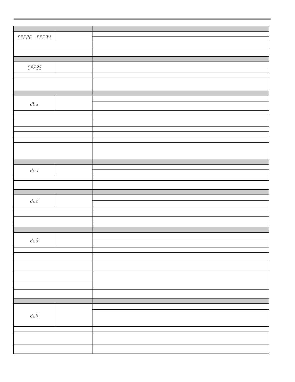
CPF26 to CPF34
Control Circuit Error
CPU error
Cause
Possible Solution
Hardware is damaged.
If the problem continues, replace the control board or the entire drive. Contact Yaskawa or a Yaskawa representative for
instructions on replacing the control board.
Digital Operator Display
Fault Name
CPF35
A/D Conversion Error
An A/D conversion error or control circuit error occurred.
Cause
Possible Solution
A/D conversion is damaged.
Control circuit is damaged.
• Cycle power to the drive.
• If the problem continues, replace the control board or the entire drive. For instructions on replacing the control board, contact
Yaskawa or your nearest sales representative.
Digital Operator Display
Fault Name
dEv
Speed Deviation (for Control Mode with Encoder)
The deviation between the speed reference and speed feedback is greater than the setting in F1-10 for longer than the time set to
F1-11.
Cause
Possible Solution
Load is too heavy.
Reduce the load.
Accel/decel ramp is too short.
Increase the acceleration and deceleration times (C1-01 through C1-08).
The load is locked up.
Check the machine.
Parameters are not set appropriately.
Check the settings of parameters F1-10 and F1-11.
The motor brake is not applied.
Ensure the motor brake operates properly with a brake control command from the drive.
During Rescue Operation, either the DC bus voltage
dropped below S4-12
× (S4-13 - 10%), or 100 ms after
triggering Rescue Operation, the DC bus voltage did not
reach S4-12
× S4-13 before the motor started.
• Check the DC bus voltage setting for Rescue Operation (S4-12).
• Lower the speed reference set for Rescue Operation (d1-25).
• Check the backup power supply. It may need to be replaced with another UPS if it has become worn and can no longer provide
enough power.
Digital Operator Display
Fault Name
dv1
Encoder Z Pulse Fault
The motor turned one full rotation without the Z Pulse being detected.
Cause
Possible Solution
Encoder is not connected, not wired properly, or is
damaged.
• Make sure the encoder is properly connected and all shielded lines are properly grounded.
• If the problem continues after cycling power, then replace either the PG option card or the encoder itself.
Digital Operator Display
Fault Name
dv2
Z Pulse Noise Fault Detection
The Z pulse is out of phase by more than 5 degrees for the number of times specified in parameter F1-17.
Cause
Possible Solution
Noise interference along the encoder cable.
Separate the encoder cable lines from the source of the noise.
Encoder cable is not wired properly.
Rewire the encoder and make sure all shielded lines are properly grounded.
PG option card or the encoder is damaged.
If the problem continues after cycling power, replace the PG option card or the encoder.
Digital Operator Display
Fault Name
dv3
Inversion Detection
The torque reference and acceleration are in opposite directions and the speed reference and actual motor speed differ by over
30% for the number of times set to F1-18.
Cause
Possible Solution
The encoder offset is not set properly to E5-11.
Set the encoder offset to E5-11 as specified on the motor nameplate. Replacing the encoder or changing the motor/encoder
rotation direction requires readjustment of the encoder offset.
An external force on the load side has caused the motor
to move.
• Make sure the motor is rotating in the right direction.
• Look for any problems on the load side that might cause the motor to rotate in the opposite direction.
Noise interference along the encoder cable is disturbing
the encoder signals.
Properly rewire the PG encoder and connect all lines including shielded line.
Encoder is disconnected, not wired properly, or the PG
option card or the encoder itself is damaged.
Rotational direction for the encoder set to F1-05 is the
opposite of the order of the motor lines.
Properly connect the motor lines for each phase (U/T1, V/T2, W/T3).
Digital Operator Display
Fault Name
dv4
Inversion Prevention Detection
Pulses indicate that the motor is rotating in the opposite direction of the speed reference. Set the number of pulses to trigger
inverse detection to F1-19.
Note: Set F1-19 to 0 to disable inverse detection in applications where the motor may rotate in the opposite direction of the speed
reference.
Cause
Possible Solution
The encoder offset is not set properly to E5-11.
• Set the encoder offset to E5-11 as specified on the motor nameplate.
• If the problem continues after cycling power, then replace either the PG option card or the encoder itself. Replacing the encoder
or changing the motor/encoder rotation direction requires readjustment of the encoder offset.
Noise interference along the encoder cable is disturbing
the encoder signals.
• Make sure the motor is rotating in the correct direction.
• Look for any problems on the load side that might be causing the motor to rotate in the opposite direction.