Using the safe disable function, Safe disable circuit, D.3 safe disable input function – Yaskawa L1000E AC Drive Technical Manual for CIMR-LE Models for Elevator Applications User Manual
Page 459
D.3 Safe Disable Input Function
YASKAWA ELECTRIC SIEP YAIL1E 01A YASKAWA AC Drive L1000E Technical Manual
459
St
an
dar
d
s
Complianc
e
D
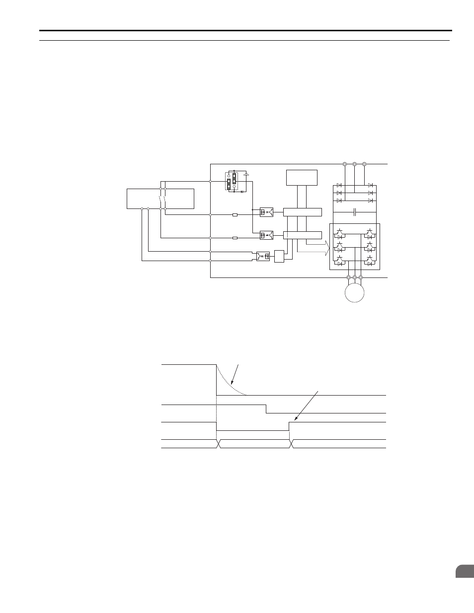
◆ Using the Safe Disable Function
■
Safe Disable Circuit
The Safe Disable circuit consists of two independent input channels that can block the output transistors (terminals H1
and H2). The input can either use the drive internal power supply or an external power supply. Use jumper S3 on the
terminal board to select between Sink or Source mode with either internal or external power supply.
A photocoupler output is available to monitor the status of the Safe Disable terminals.
for signal specifications when using this output.
Additionally a Safe Disable monitor function can be assigned to one of the digital outputs (H2- = 58).
Figure D.3
Figure D.3 Safe Disable Function Wiring Example (Source Mode)
■
Disabling and Enabling the Drive Output (“Safe Torque Off”)
illustrates a Safe Disable input operation example.
Figure D.4
Figure D.4 Safe Disable Operation
Entering the “Safe Torque Off” State
Whenever either one Safe Disable input or both inputs open, the motor torque is shut off by switching off the drive output.
If the motor was running before the Safe Disable inputs opened, it will coast to stop, regardless of the stopping method set
in parameter b1-03.
Notice that the “Safe Torque Off” state can only be achieved using the Safe Disable function. Removing the Up/Down
command stops the drive and shuts the output off (baseblock), but does not create a “Safe Torque Off” status.
Note: To avoid an uncontrolled stop during normal operation, make sure that the Safe Disable inputs are opened first when the motor
has completely stopped.
Safety
Outputs
Power Module P
N
M
Gate Block 2
Gate Block 1
Control
Circuit
Main Power
H1
H2
HC
Drive
Jumper S3
Setting:
SOURCE
>=1
DM+
DM-
Feedback
Safety Relay or PLC
with safety functionality
24 Vdc
H1, H2 Input
Drive Output
ON (Safe Disable off)
Normal operation
OFF (Safe Disable activated)
Safe Torque-Off
Up/Down Command
Run
Stop
Baseblock (Not Safe!)
Output
Frequency
Motor coasts
to stop
Drive is ready for
operation