12 wiring checklist – Yaskawa L1000E AC Drive Technical Manual for CIMR-LE Models for Elevator Applications User Manual
Page 83
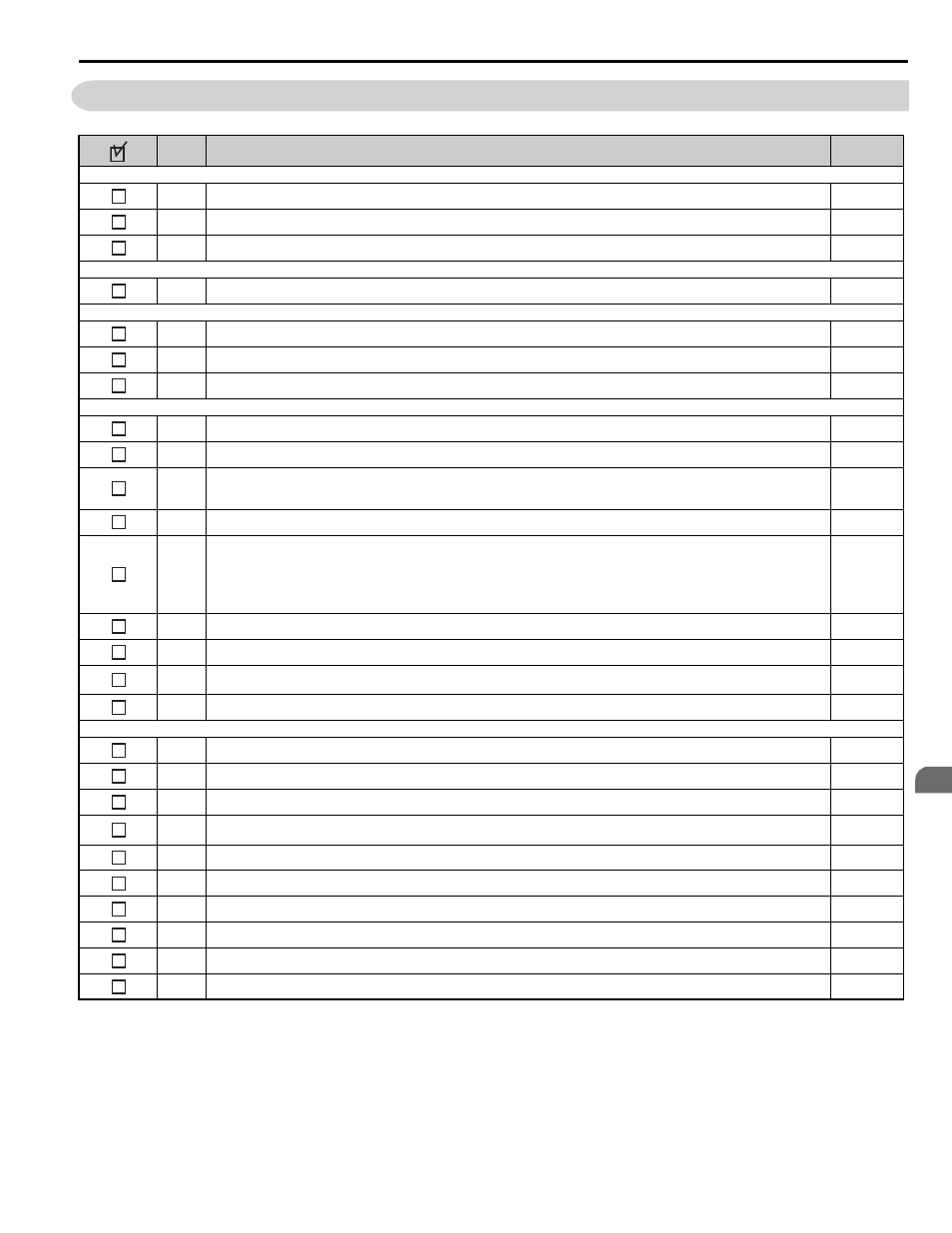
3.12 Wiring Checklist
YASKAWA ELECTRIC SIEP YAIL1E 01A YASKAWA AC Drive L1000E Technical Manual
83
El
ec
tr
ic
al
In
st
al
la
ti
o
n
3
3.12 Wiring Checklist
No.
Item
Page
Drive, peripherals, option cards
1
Check drive model number to ensure receipt of correct model.
–
2
Make sure you have the correct braking resistors, DC link choke, noise filters, and other peripheral devices installed.
3
Check the option card model number.
Installation area and physical setup
4
Ensure that the area surrounding the drive complies with specifications.
Power supply voltage, output voltage
5
The voltage from the power supply should be within the input voltage specification range of the drive.
6
The voltage rating for the motor should match the drive output specifications.
7
Verify that the drive is properly sized to run the motor.
Main circuit wiring
8
Confirm proper branch circuit protection as specified by national and local codes.
9
Properly wire the power supply to drive terminals R/L1, S/L2, and T/L3.
10
Properly wire the drive and motor together.
The motor lines and drive output terminals R/T1, V/T2, and W/T3 should match in order to produce the desired phase order. If the phase order
is incorrect, the drive will rotate in the opposite direction.
11
Use 600 Vac vinyl-sheathed wire for the power supply and motor lines.
12
Use the correct wire gauges for the main circuit. .
• Consider the amount of voltage drop when selecting wire gauges. Increase the wire gauge when the voltage drop is greater than 2% of motor
rated voltage. Ensure the wire gauge is suitable for the terminal block. Use the following formula to calculate the amount of voltage drop:
Line drop voltage (V) = 3
× wire resistance (Ω/km) × wire length (m) × current (A) × 10
-3
• If the cable between the drive and motor exceeds 50 m (164 feet), adjust the carrier frequency set to C6-02 accordingly.
13
Properly ground the drive.
14
Tightly fasten all terminal screws (control circuit terminals, grounding terminals)..
15
Install a magnetic contactor when using a dynamic braking option. Properly install the resistor and ensure that overload protection shuts off the
power supply using the magnetic contactor.
16
Verify phase advancing capacitors, input noise filters, or ground fault circuit interrupters are NOT installed on the output side of the drive.
–
Control circuit wiring
17
Use twisted-pair line for all drive control circuit wiring.
18
Connect the shields of shielded wiring to the ground terminal (E [G]).
19
Properly wire any option cards.
20
Check for any other wiring mistakes.
Only use a multimeter to check wiring.
–
21
Properly fasten the control circuit terminal screws in the drive..
22
Pick up all wire clippings.
–
23
Ensure that no frayed wires on the terminal block are touching other terminals or connections.
–
24
Properly separate control circuit wiring and main circuit wiring.
–
25
Analog signal line wiring should not exceed 50 m (164 ft.).
–
26
Safe Disable input wiring should not exceed 30 m (98 ft.).
–