U6: control monitors, B.3 parameter table – Yaskawa L1000E AC Drive Technical Manual for CIMR-LE Models for Elevator Applications User Manual
Page 409
B.3 Parameter Table
YASKAWA ELECTRIC SIEP YAIL1E 01A YASKAWA AC Drive L1000E Technical Manual
409
Pa
ra
met
er
L
is
t
B
Note: Fault trace (i.e., the fault history) is not maintained when CPF00, CPF01, CPF06, CPF24, oFA00, oFb00, oFC00, Uv1, Uv2, or Uv3
occur.
■
U6: Control Monitors
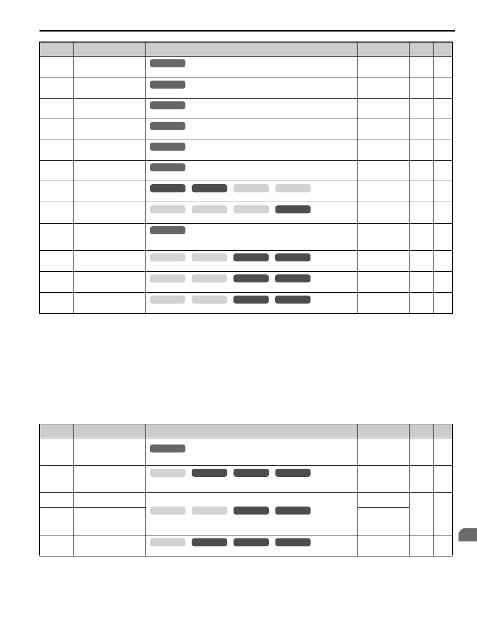
U4-24
(7E6H)
Number of Travels
(Lower 4 digit)
Displays the lower four digits for the number of trips the drive has made.
No signal output
available
1 time
–
U4-25
(7E7H)
Number of Travels
(Higher 4 digit)
Displays the upper four digits for the number of trips the drive has made.
No signal output
available
1 time
–
U4-26
(7E8H)
Max. Current during
Acceleration
Shows the maximum current that occurred during acceleration.
No signal output
available
0.1 A
–
U4-27
(7E9H)
Max. Current during
Deceleration
Shows the maximum current that occurred during deceleration.
No signal output
available
0.1 A
–
U4-28
(7EAH)
Max. Current during Constant
Speed
Shows the maximum current that occurred during ride at top speed.
No signal output
available
0.1 A
–
U4-29
(7EDH)
Max. Current during Leveling
Speed
Shows the maximum current that occurred during ride at leveling speed.
No signal output
available
0.1 A
–
U4-30
(7EEH)
Slip Compensation Value
Shows the slip compensation value.
No signal output
available
0.01%
–
U4-31
(7EFH)
Car Acceleration Rate
Shows the car acceleration rate.
No signal output
available
0.01 m/s
2
–
U4-40
(7FDH)
Speed Reference Limit at
Rescue Operation
Displays the speed limit for Rescue Operation based on how much power the backup battery or
UPS has. Displays 0% when Rescue Operation is not being performed.
No signal output
available
1%
–
U4-42
(855H)
Remaining Distance
Displays the remaining distance according to the stopping method selected.
10 V:
S5-10 = 1: S5-11
S5-10 = 2: S5-12
1 mm
–
U4-43
(856H)
Minimum Deceleration
Distance
Displays the Minimum Deceleration Distance calculated by E1-04.
No signal output
available
1 mm
–
U4-44
(857H)
Minimum Stop Distance
Displays the Minimum Stop Distance calculated by d1-26.
No signal output
available
1 mm
–
<31> Setting units are determined by the digital operator display unit selection (o1-03). When o1-03 = 0, the value is set in Hertz. When o1-03 = 4
or 5, the value is displayed in m/s. When o1-03 = 6, the value is displayed in ft/min.
<35> o1-12 (Length Units) determines the units. When o1-12 is set to 0, the unit is millimeters. When o1-12 is set to 1, the unit is inch.
<40> When checking the values of U1-03, U2-05 and U4-13 with the digital operator they are displayed in units of amperes, but when they are
checked using MEMOBUS communications, the monitor value in MEMOBUS communications is: displayed numeric value / 8192
× drive’s
rated current (A), from the condition “8192 (maximum value) = drive’s rated current (A)”.
<41> The MEMOBUS communications data is in 10 h units. If data in 1 h units are also required, refer to register number 0099H.
<42> The MEMOBUS communications data is in 10 h units. If data in 1 h units are also required, refer to register number 009BH.
No. (Addr.)
Name
Description
Analog Output
Level
Unit
Page
U6-01
(51H)
Motor Secondary Current (Iq)
Displays the value of the motor secondary current (Iq). Motor rated secondary current is 100%.
10 V: Motor
secondary rated
current
(-10 to +10 V)
0.1%
–
U6-02
(52H)
Motor Excitation Current (Id)
Displays the value calculated for the motor excitation current (Id). Motor rated secondary
current is 100%.
10 V: Motor
secondary rated
current
(-10 to +10 V)
0.1%
–
U6-03
(54H)
Speed Control Loop Input
Displays the input and output values of the speed control loop.
10 V: Max frequency
(-10 to +10 V)
0.01%
–
U6-04
(55H)
Speed Control Loop Output
10 V: Motor
secondary rated
current
(-10 to +10 V)
U6-05
(59H)
Output Voltage Reference (Vq)
Output voltage reference (Vq) for the q-axis.
10 V: 200 Vrms
(-10 to +10 V)
0.1 Vac
–
No. (Addr.)
Name
Description
Analog Output
Level
Unit
Page
All Modes
common
_
All Modes
common
_
All Modes
common
_
All Modes
common
_
All Modes
common
_
All Modes
common
_
common
_
CLV
CLV/PM
V/f
OLV
common
_
CLV
CLV/PM
V/f
OLV
All Modes
common
_
CLV
CLV/PM
V/f
OLV
common
_
CLV
CLV/PM
V/f
OLV
common
_
CLV
CLV/PM
V/f
OLV
common
_
All Modes
common
_
common
_
CLV
CLV/PM
V/f
OLV
common
_
CLV
CLV/PM
V/f
OLV
common
_
CLV
CLV/PM
V/f
OLV