3 fault detection – Yaskawa L1000E AC Drive Technical Manual for CIMR-LE Models for Elevator Applications User Manual
Page 285
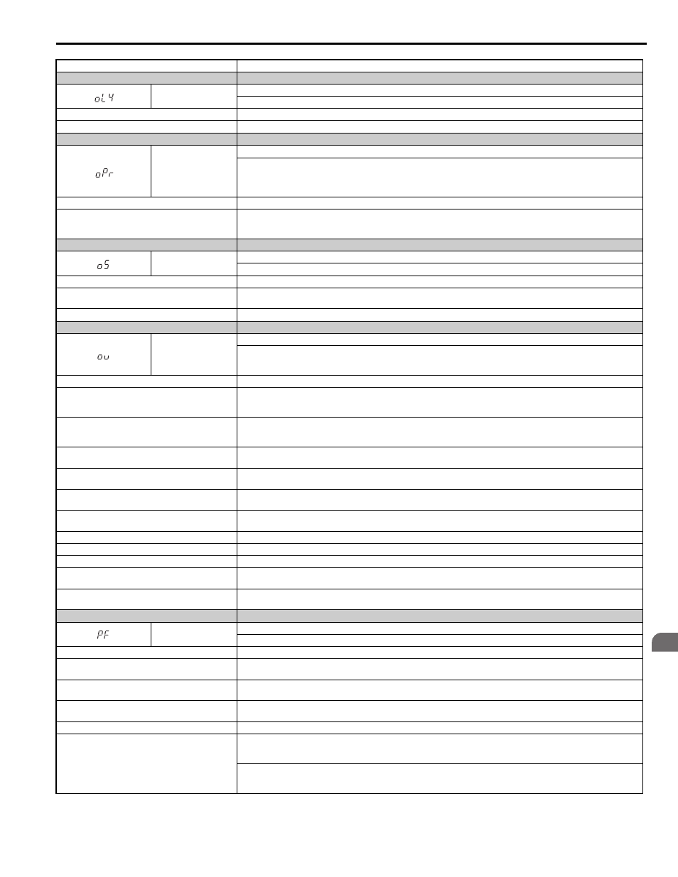
6.3 Fault Detection
YASKAWA ELECTRIC SIEP YAIL1E 01A YASKAWA AC Drive L1000E Technical Manual
285
T
ro
ubles
hoo
ting
6
Fault on the machine side (e.g., machine is locked up).
Check the status of the load. Remove the cause of the fault.
Digital Operator Display
Fault Name
oL4
Overtorque Detection 2
The current has exceeded the value set for Overtorque Detection 2 (L6-05) for longer than the allowable time (L6-06).
Cause
Possible Solution
Parameter settings are not appropriate for the load.
Check the settings of parameters L6-05 and L6-06.
Digital Operator Display
Fault Name
oPr
External Digital Operator Connection Fault
• The external operator has been disconnected from the drive.
Note: An oPr fault will occur when all of the following conditions are true:
• Output is interrupted when the operator is disconnected (o2-06 = 1).
• The Up/Down command is assigned to the operator (b1-02 = 0 and LOCAL has been selected).
Cause
Possible Solution
External operator is not properly connected to the drive.
• Check the connection between the operator and the drive.
• Replace the cable if damaged.
• Turn off the drive input power and disconnect the operator. Then reconnect the operator and turn the drive input power back on.
Digital Operator Display
Fault Name
oS
Overspeed
The motor speed feedback exceeded the F1-08 setting.
Cause
Possible Solution
Overshoot is occurring.
• Reduce the settings for C5-01 (Speed Control Proportional Gain 1) and increase C5-02 (Speed Control Integral Time 1).
• If using a closed loop vector mode, enable Inertia Compensation.
Inappropriate parameter settings.
Check the setting for the overspeed detection level and the overspeed detection time (F1-08 and F1-09).
Digital Operator Display
Fault Name
ov
DC Bus Overvoltage
Voltage in the DC bus has exceeded the overvoltage detection level.
• For 200 V class: approximately 410 V
• For 400 V class: approximately 820 V
Cause
Possible Solution
Deceleration ramp is too short and regenerative energy
is flowing from the motor into the drive.
• Increase the deceleration ramp (C1-02, C1-04, C1-06, C1-08).
• Make sure the braking resistor rating/external braking transistor rating fits the application.
• If an external braking transistor is used, make sure it is connected properly and working as expected.
Fast acceleration ramp causes the motor to overshoot the
speed reference.
• Check if sudden drive acceleration triggers an overvoltage alarm.
• Increase the acceleration ramp (C1-01, C1-03, C1-05, C1-07).
• Increase the jerk setting in C2-02 (decrease if o1-03
> 3)
Surge voltage entering from the drive input power.
Install a DC link choke.
Note: Voltage surge can result from a thyristor convertor and phase advancing capacitor using the same input power supply.
Ground fault in the output circuit causes the DC bus
capacitor to overcharge.
• Check the motor wiring for ground faults.
• Correct grounding shorts and turn the power back on.
Drive input power voltage is too high.
• Check the voltage.
• Lower drive input power voltage within the limits listed in the specifications.
The braking transistor is wired incorrectly.
• Check braking transistor wiring for errors.
• Properly rewire the braking resistor device.
Encoder cable is disconnected.
Reconnect the cable.
Encoder cable wiring is wrong.
Correct the wiring.
Noise interference along the encoder wiring.
Separate the wiring from the source of the noise (often the output lines from the drive).
Drive fails to operate properly due to noise interference.
• Review the list of possible solutions provided for controlling noise.
• Review the section on handling noise interference and check the control circuit lines, main circuit lines, and ground wiring.
Motor hunting occurs.
• Adjust the parameters that control hunting.
• Adjust the AFR time constant (n2-02 and n2-03).
Digital Operator Display
Fault Name
PF
Input Phase Loss
Drive input power has an open phase or has a large imbalance of voltage between phases. Detected when L8-05 = 1 (enabled).
Cause
Possible Solution
There is phase loss in the drive input power.
• Check for wiring errors in the main circuit drive input power.
• Correct the wiring.
There is loose wiring in the drive input power terminals.
• Ensure the terminals are tightened properly.
• Apply the tightening torque as specified in this manual.
Refer to Wire Gauges and Tightening Torque on page 64
There is excessive fluctuation in the drive input power
voltage.
• Check the voltage from the drive input power.
• Review the possible solutions for stabilizing the drive input power.
There is poor balance between voltage phases.
• Stabilize drive input power or disable phase loss detection.
The main circuit capacitors are worn.
• Check the maintenance time for the capacitors (U4-05).
• Replace the capacitor if U4-05 is greater than 90%. For instructions on replacing the capacitor, contact Yaskawa or a Yaskawa
representative.
Check for problems with the drive input power. If drive input power appears normal but the alarm continues to occur, replace
either the control board or the entire drive. For instructions on replacing the control board, contact Yaskawa or a Yaskawa
representative.