3 main circuit connection diagram, Y e a _ c o m – Yaskawa L1000E AC Drive Technical Manual for CIMR-LE Models for Elevator Applications User Manual
Page 57
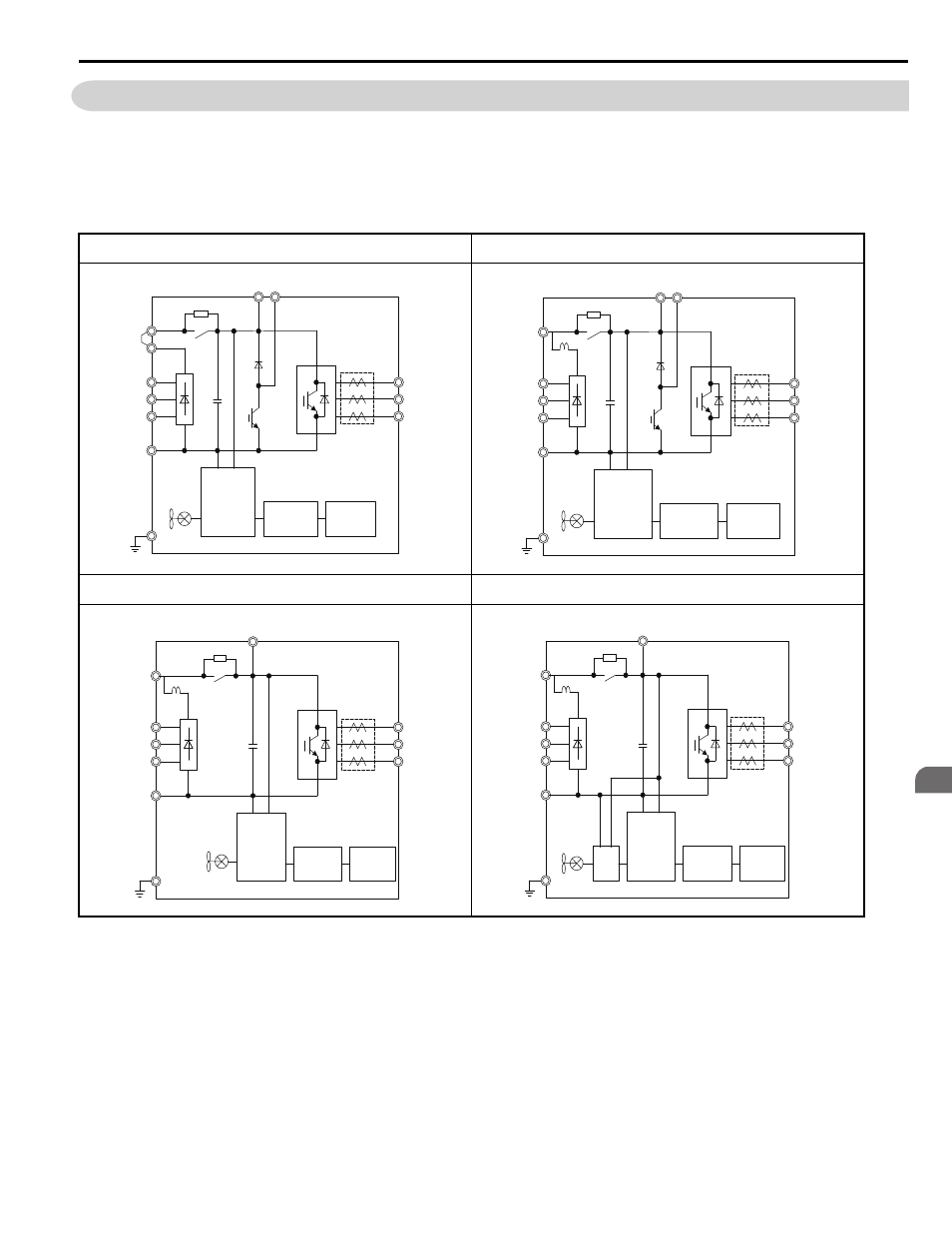
3.3 Main Circuit Connection Diagram
YASKAWA ELECTRIC SIEP YAIL1E 01A YASKAWA AC Drive L1000E Technical Manual
57
El
ec
tr
ic
al
In
st
al
la
ti
o
n
3
3.3 Main Circuit Connection Diagram
Refer to the
when wiring the main circuit of the drive. Connections may vary based on drive capacity. The DC
power supply for the main circuit also provides power to the control circuit.
NOTICE: Do not use the negative DC bus terminal “-” as a ground terminal. This terminal is at high DC voltage potential. Improper
wiring connections could damage the drive.
Figure 3.2 Drive Main Circuit Configurations
2A0018 to 2A0094
4A0009 to 4A0049
2A0106 and 2A0144
4A00456 and 4A0075
2A0181 and 2A0225
4A0094 to 4A0140
2A0269 to 2A0432
4A0188 to 4A0260
+1
+2
–
R/L1
S/L2
T/L3
Relay
Gate board
Control
board
Operator
+
Current
sensor
U/T1
V/T2
W/T3
B1 B2
+1
–
R/L1
S/L2
T/L3
U/T1
V/T2
W/T3
B1 B2
DC link
choke
+
Relay
Gate board
Control
board
Operator
Current
sensor
Y E A _
c o m -
+1
–
R/L1
S/L2
T/L3
U/T1
V/T2
W/T3
+
+3
DC link
choke
Relay
Gate board
Control
board
Operator
Current
sensor
Y E A _
c o m -
+1
–
R/L1
S/L2
T/L3
U/T1
V/T2
W/T3
+3
+
24 V
Power
Supply
DC link
choke
Relay
Gate board
Control
board
Operator
Current
sensor
Y E A _
c o m -