10 o: operator related settings, O1: digital operator display selection, O1-01: drive mode unit monitor selection – Yaskawa L1000E AC Drive Technical Manual for CIMR-LE Models for Elevator Applications User Manual
Page 239: O1-02: user monitor selection after power up, O1-03: digital operator display unit selection
5.10 o: Operator Related Settings
YASKAWA ELECTRIC SIEP YAIL1E 01A YASKAWA AC Drive L1000E Technical Manual
239
P
a
ra
me
te
r De
ta
ils
5
5.10 o: Operator Related Settings
These parameters control the various functions, features, and display of the digital operator.
◆ o1: Digital Operator Display Selection
These parameters determine the data display on the digital operator.
■
o1-01: Drive Mode Unit Monitor Selection
When using an LED operator, pressing the up arrow key will display the following data: speed reference
→ rotational
direction
→ output speed → output current → o1-01 selection.
Parameter o1-01 selects the content of the last monitor in this sequence. This is done by entering the 1 part of
U1-. There is no effect like this on an LCD operator.
■
o1-02: User Monitor Selection after Power Up
Selects which monitor parameter is displayed upon power up. Certain monitors are not available in some control modes.
Refer to U: Monitor Parameters on page 265
for a list of monitors.
Setting 1: Speed reference (U1-01)
Setting 2: Motor direction
Setting 3: Output speed (U1-02)
Setting 4: Output current (U1-03)
Setting 5: User-selected monitor (set by o1-01)
If o1-02 is set to 5, o1-01 can be used to change the content of this monitor.
■
o1-03: Digital Operator Display Unit Selection
Sets the units used to display speed related settings and monitors as well as accel/decel rate settings and jerk settings.
Refer to Digital Operator Display Unit Selection on page 105
.
Setting 0: 0.01 Hz units
Setting 1: 0.01% units (100% = max. output frequency)
Setting 2: r/min units (calculated by the max output frequency and the no. of motor poles)
Setting 3: User-set units (use o1-10, o1-11)
Set o1-03 to 3 for user-set units, then set parameters o1-10 and o1-11.
Set the value use for the maximum frequency reference to o1-10. The placement of the decimal point in this number
should be set to o1-11.
For example, to have the maximum output speed displayed as “100.00”, set the o1-10 = 1000 and o1-11 = 2 (i.e., 1000
with 2 decimal points).
Setting 4: Elevator units 1 (speed in m/s, accel/decel rate and jerk in s)
Setting 5: Elevator units 2 (speed in m/s, accel/decel rate in m/s
2
, jerk in m/s
3
)
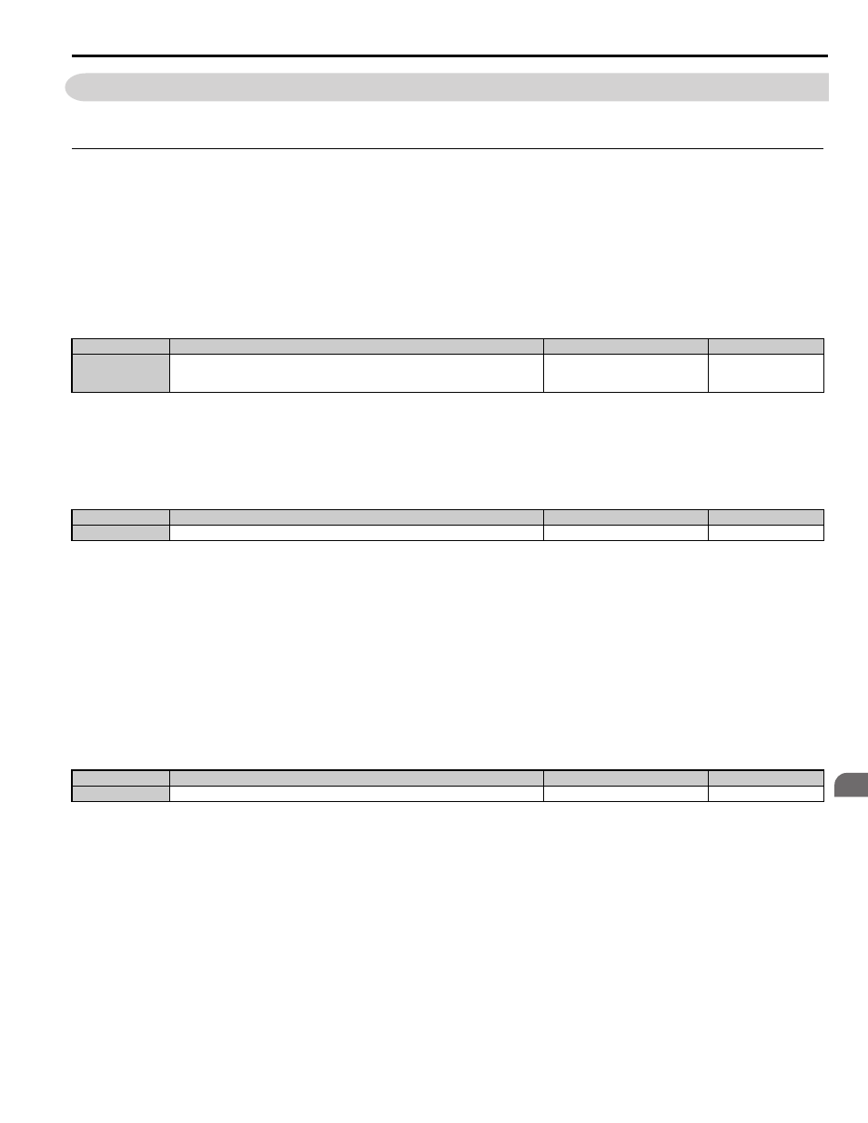
No.
<1> U2- and U3- parameters cannot be selected.
Parameter Name
Setting Range
Default
o1-01
Drive Mode Unit Monitor Selection
105 to 699
U1-04 (Control Mode) to
U6-99 (Option Monitor 20)
106 (U1-06)
No.
Parameter Name
Setting Range
Default
o1-02
User Monitor Selection after Power Up
1 to 5
1
No.
Parameter Name
Setting Range
Default
o1-03
Digital Operator Display Unit Selection
0 to 6
1