L5: automatic fault reset, Terminal set to 1e will open, L4-13: door zone level – Yaskawa L1000E AC Drive Technical Manual for CIMR-LE Models for Elevator Applications User Manual
Page 221: Common_ tmonly, 8 l: protection functions

5.8 L: Protection Functions
YASKAWA ELECTRIC SIEP YAIL1E 01A YASKAWA AC Drive L1000E Technical Manual
221
P
a
ra
me
te
r De
ta
ils
5
■
L4-13: Door Zone Level
Sets the speed level for the car door to open. Once the car slows to the speed set in L4-13, a multi-function output terminal
set for “Door zone reached” will close (H2- = 52).
◆ L5: Automatic Fault Reset
After a fault has occurred, Fault Restart attempts to automatically restart the motor and continue operation instead of
stopping. The inverter can reset faults automatically. The maximum number of resets can be selected as well as the
operation mode of the fault relay.
WARNING! Sudden Movement Hazard. Do not use the fault reset function in lifting applications. Fault reset may cause the machine to
drop the load, which could result in death or serious injury.
Faults Allowing for Automatic
Reset
The drive attempts to reset itself after one of the faults listed below has occurred. All other faults will need to be reset
externally.
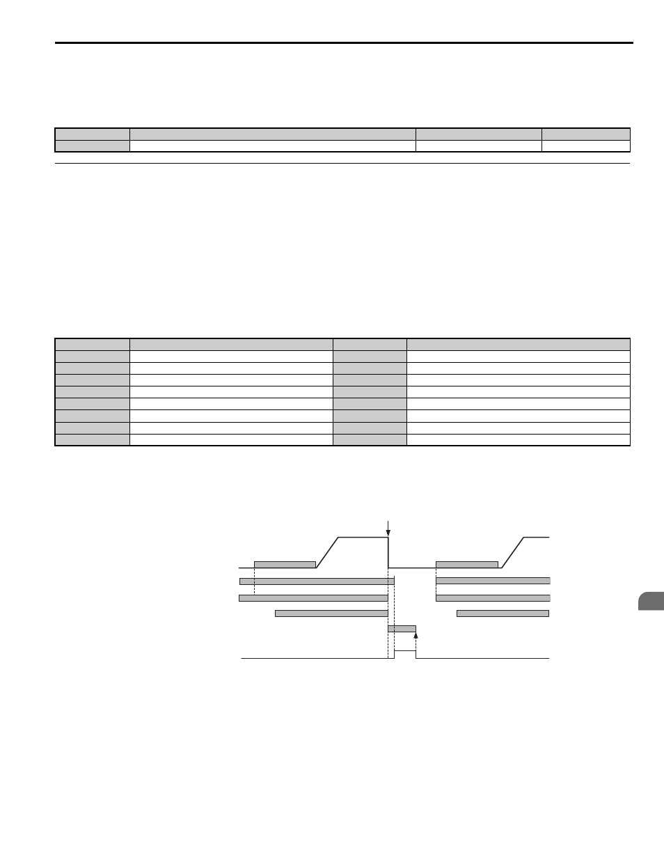
Fault Reset Time Chart
Parameter L5-01 sets the number of times the drive can attempt to reset itself after on of the faults in the table above
occurs. The time chart below illustrates how fault reset works.
Figure 5.38
Figure 5.38 Fault Reset Time Chart
<1> The drive will accept an auto reset signal once the Up and Down commands have been removed.
<2> Software baseblock (H1- = 8, or 9) can also be used instead of Safe Disable inputs
Use parameter L5-06 to set up automatic fault reset.
To output a signal during fault reset, set one of the output terminals to "Reset enabled" (H2- = 1E).
No.
Parameter Name
Setting Range
Default
L4-13
Door Zone Level
0.0 to 100.0%
0.0%
Fault
Name
Fault
Name
GF Ground
Fault
ov DC
Bus
Overvoltage
LF
Output Phase Loss
rr
Braking Transistor Fault
oC Overcurrent
UL3
Undertorque Detection 1
oH1
Heatsink Overheat
UL4
Undertorque Detection 2
oL1 Motor
Overload
SE1
Sequence Error 1
oL2 Drive
Overload
SE2
Sequence Error 2
oL3
Overtorque Detection 1
SE3
Sequence Error 3
oL4
Overtorque Detection 2
–
–
Up or Down command
DC Injection/
Position Lock
Safe Disable Inputs (H1-HC, H2-HC)
<2>
Brake Control (H2-
= 50)
DC Injection/
Position Lock
Fault (H2-
= E)
Fault
Auto Reset
<1>
Output Speed
common_
TMonly