C1-11: accel/decel switching speed, C1-09: fast stop ramp, Common_tmo – Yaskawa L1000E AC Drive Technical Manual for CIMR-LE Models for Elevator Applications User Manual
Page 163: 3 c: tuning
5.3 C: Tuning
YASKAWA ELECTRIC SIEP YAIL1E 01A YASKAWA AC Drive L1000E Technical Manual
163
P
a
ra
me
te
r De
ta
ils
5
Switching Acceleration and Deceleration Times by Motor Selection
When switching between motor 1 and 2 using a digital input (H1-= 16), parameters C1-01 to C1-04 become accel/
decel times 1 and 2 for motor 1, while C1-05 to C1-08 become accel/decel times 1 and 2 for motor 2. Accel/decel times 1
and 2 can be switched for each motor using a digital inputs set to H1- = 7 like shown in
Note: 1. The motor 2 selection function cannot be used when PM motor is used.
2. The digital input setting “Accel/Decel time 2 selection” (H1- = 1A) cannot be used together with motor 1/2 switching. Trying to
do so triggers an oPE03 error, indicating a contradictory multifunction input settings.
3. The acceleration rate switch is disabled if the S3-21 “Dwell 2 End Speed” is set to any other value other than 0.
Table 5.7 Motor Switching and Accel/Decel Time Combinations
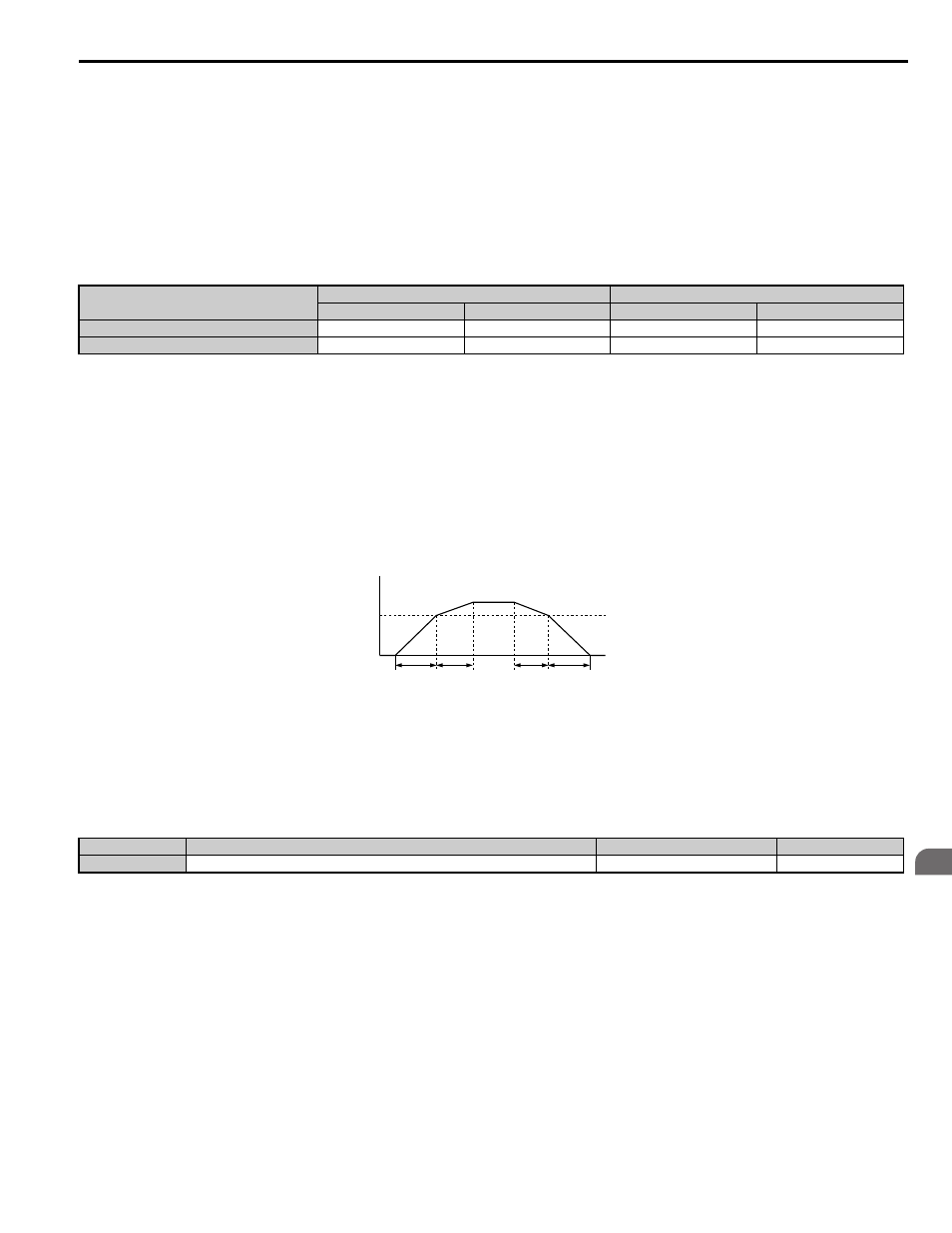
Switching Accel/Decel Ramps by a Speed Level
The drive can switch between different acceleration and deceleration ramps automatically. The drive will switch from
accel/decel ramp 4 in C1-07 and C1-08 to the default accel/decel ramp in C1-01 and C1-02 when the output speed
exceeds the speed level set in parameter C1-11. When it falls below this level, the accel/decel ramps are switched back.
shows an operation example.
Note: 1. Acceleration and deceleration ramps selected by digital inputs have priority over the automatic switching by the speed level set to C1-
11. For example, if accel/decel ramp 2 is selected, the drive will use this time only and not switch from accel/decel ramp 4 to the
selected one.
2. The acceleration rate switch is disabled if the S3-21 (Dwell 2 End Speed) is set to any other value other than 0.
Figure 5.6
Figure 5.6 Accel/Decel Switching Speed
■
C1-11: Accel/Decel Switching Speed
Sets the speed at which the drive switches between accel/decel ramp settings.
Refer to Switching Accel/Decel Ramps by
Note: Setting C1-11 to 0.0% disables this function.
■
C1-09: Fast Stop Ramp
Sets a special deceleration used when a select group of faults occur or when closing a digital input configured as H1-
= 15 (N.O. input) or 17 (N.C. input). A momentary closure of the digital input will trigger the Fast Stop operation; it does
not have to be closed continuously. The drive cannot be restarted after initiating a Fast Stop operation until after
completing deceleration, clearing the Fast Stop input, and cycling the Up/Down command.
A Fast Stop can be selected as the action the drive should take when certain faults occur, such as L8-03 (Overheat Pre-
Alarm Operation Selection).
Accel/Decel Time 1 (H1- = 7)
Motor 1 Selected (Terminal set to H1-=16 OFF)
Motor 2 Selected (Terminal set to H1-=16 ON)
Accel
Decel
Accel
Decel
Open
C1-01
C1-02
C1-05
C1-06
Closed
C1-03
C1-04
C1-07
C1-08
No.
Parameter Name
Setting Range
Default
C1-11
Accel/Decel Switching Speed
0.0 to 100.0%
0.0%
Output Speed
C1-11
Accel/Decel
Switching Speed
C1-07
setting
When the output speed ≥ C1-11, drive uses Accel/Decel Ramp 1 (C1-01, -02)
When the output speed < C1-11, drive uses Accel/Decel Ramp 2 (C1-07, -08)
C1-01
setting
C1-02
setting
C1-08
setting
common_TMo