E3: v/f pattern for motor 2, Common_tmo, 5 e: motor parameters – Yaskawa L1000E AC Drive Technical Manual for CIMR-LE Models for Elevator Applications User Manual
Page 182
5.5 E: Motor Parameters
182
YASKAWA ELECTRIC SIEP YAIL1E 01A YASKAWA AC Drive L1000E Technical Manual
Setting the Motor Iron-Core Saturation Coefficient 1, 2
E2-07 and E2-08 are set when Auto-Tuning is performed.
Setting the Motor Mechanical Loss
Only required in Closed Loop Vector Control. The drive compensates for the degree of mechanical loss with torque
compensation. Although E2-09 rarely needs to be changed, adjustment may benefit when there is a large amount of
torque loss due to motor bearing friction.
Setting the Motor Iron Loss for Torque Compensation
Only required when using V/f Control. Enter this value in watts to E2-10. The drive uses this setting to improve the
precision of torque compensation.
◆ E3: V/f Pattern for Motor 2
These parameters set the V/f pattern used for motor 2.
Refer to Setting 16: Motor 2 selection on page 195
switching motors.
Note: The function for switching between two motors cannot be used with a PM motor. E3- parameters are hidden when a PM
motor control mode is selected (A1-02 = 7).
■
E3-04 to E3-10
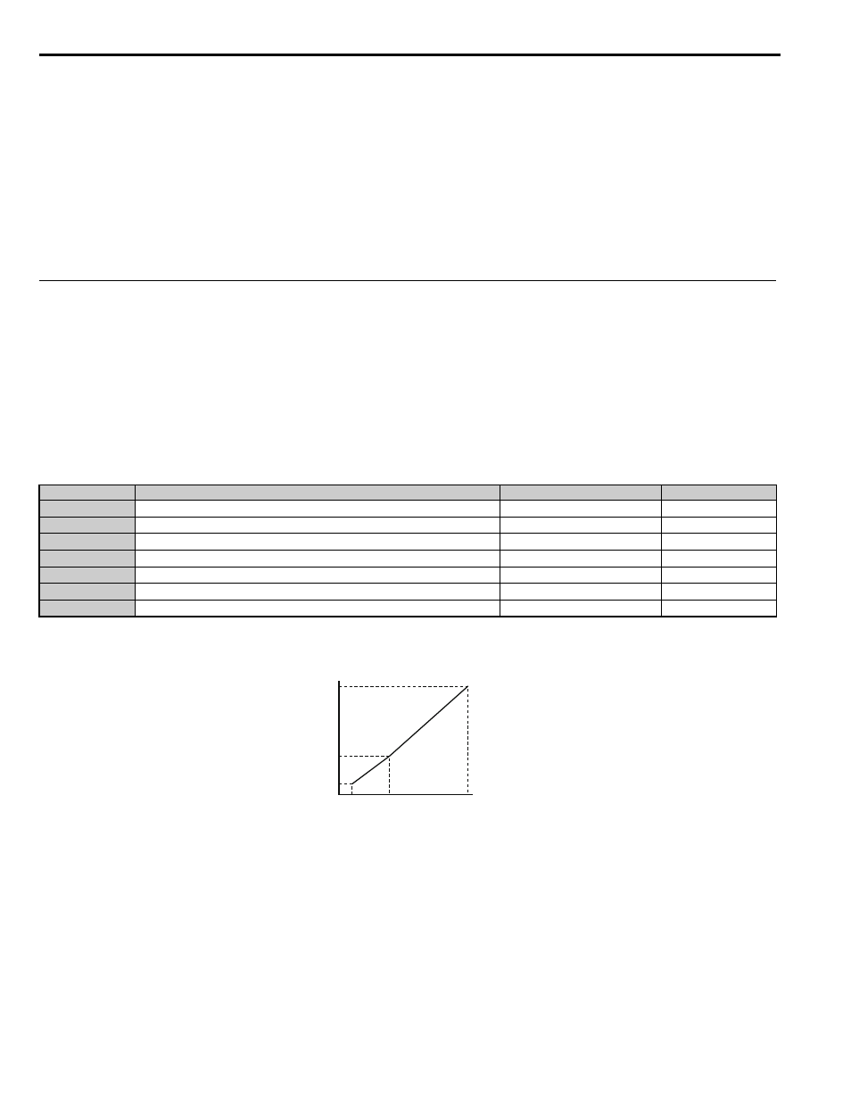
Parameters E3-04 through E3-10 set up the V/f pattern used for motor 2 as shown in
.
Note: Certain E3- parameters might not be visible depending on the control mode.
Refer to Parameter List on page 365
for details.
Figure 5.14
Figure 5.14 V/f Pattern for Motor 2
Note: 1. The following conditions must be true when setting up the V/f pattern: E3-09
≤ E3-07 < E3-06 ≤ E3-04
2. To make the V/f pattern a straight line at a frequency lower than E3-07, set E3-09 equal to E3-07. In this case the E3-08 setting is
disregarded.
3. Parameters E3-04 through E3-10 are reset to their default values when the drive is initialized.
No.
<1> Values shown here are for 200 V class drives. Double the value when using a 400 V class drive.
<2> Default setting value is dependent on the drive model (o2-04).
Parameter Name
Setting Range
Default
E3-04
Motor 2 Max Output Frequency
10.0 to 120.0 Hz
60.0 Hz
E3-05
Motor 2 Max Voltage
0.0 to 255.0 V
230.0 V
E3-06
Motor 2 Base Frequency
0.0 to 120.0 Hz
60.0 Hz
E3-07
Motor 2 Mid Output Frequency
0.0 to 120.0 Hz
3.0 Hz
E3-08
Motor 2 Mid Output Frequency Voltage
0 to 255.0 V
E3-09
Motor 2 Minimum Output Frequency
0.0 to 120.0 Hz
1.5 Hz
E3-10
Motor 2 Minimum Output Frequency Voltage
0.0 to 255.0 V
Output (V)
Frequency (Hz)
E3-05
E3-08
E3-10
E3-09
E3-07
E3-04
common_TMo