Power on, Control mode selection, Power on control mode selection – Yaskawa L1000E AC Drive Technical Manual for CIMR-LE Models for Elevator Applications User Manual
Page 103: 4 start-up flowcharts
4.4 Start-Up Flowcharts
YASKAWA ELECTRIC SIEP YAIL1E 01A YASKAWA AC Drive L1000E Technical Manual
103
St
ar
t-
U
p
Pr
og
ra
m
m
in
g
&
Op
er
at
io
n
4
◆ Power On
Take the following precautions before applying main power to the drive:
WARNING! Sudden Movement Hazard. Ensure start/stop, I/O and safety circuits are wired properly and in the correct state before
energizing or running the drive. Failure to comply could result in death or serious injury from moving equipment.
WARNING! Fire Hazard. Do not use an improper voltage source. Failure to comply could result in death or serious injury by fire. Verify
that the rated voltage of the drive matches the voltage of the incoming power supply before applying power.
WARNING! Fire Hazard. Loose electrical connections could result in death or serious injury by fire due to overheating of electrical
connections. Tighten all terminal screws to the specified tightening torque.
WARNING! Fire Hazard. Do not connect the AC power line to the output motor terminals of the drive. Failure to comply could result in
death or serious injury by fire as a result of drive damage from line voltage application to output terminals.
• Do not connect AC line power to output terminals U/T1, V/T2, and W/T3.
• Make sure that the power supply lines are connected to main circuit input terminals R/L1, S/L2, and T/L3
(or R/L1 and S/L2 for single-phase power).
WARNING! Sudden Movement Hazard. Clear personnel, secure equipment and check sequence and safety circuitry before starting
the drive. Failure to comply could result in death or serious injury from moving equipment.
• Clear all personnel from the drive, motor, and machine area.
• Secure covers, couplings, shaft keys, and machine loads.
• Ensure start/stop and safety circuits are wired properly and in the correct state.
WARNING! Sudden Movement Hazard. Operating a drive with untested emergency circuits could result in death or serious injury.
Always check the operation of drive fast stop circuits and any additional emergency circuits after they are wired. Fast stop circuits are
required to provide safe and quick shutdown of the drive.
NOTICE: Equipment Hazard. Comply with proper wiring practices. The motor may run in reverse if the phase order is backward.
Connect motor input terminals U/T1, V/T2, and W/T3 to drive output terminals U/T1,V/T2, and W/T3. The phase order for the drive and
motor should match.
NOTICE: Equipment Hazard. Check all the wiring including the PG encoder wiring and PG option jumper settings, to ensure that all
connections are correct after installing the drive and connecting any other devices. Failure to comply could result in damage to the
drive.
After applying the power, the drive mode display should appear and no fault or alarm should be displayed.
Alarms, Faults, and Errors on page 270
in the event of a drive fault or error code.
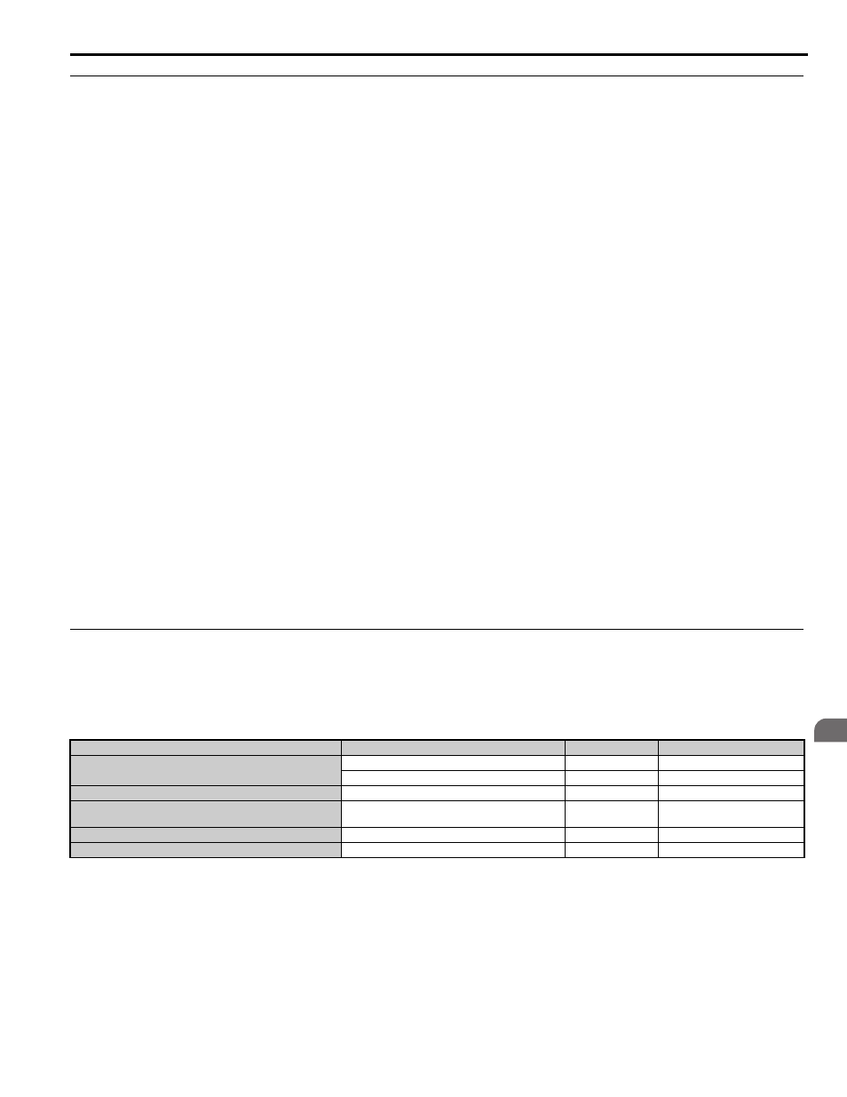
◆ Control Mode Selection
Select one of the four motor control modes after applying power to the drive. Note that Closed Loop Vector modes require
PG encoder feedback cards. The table below indicates possible control modes depending on the motor type and shows the
required encoder feedback card.
Machine Type
Control Mode
A1-02 setting
Encoder Option Card
Induction motor without encoder
V/f Control
0
No card required
Open Loop Vector Control
2
No card required
Induction motor with incremental encoder
Closed Loop Vector Control
3
PG-B3 / PG-X3
Permanent magnet motor with EnDat 2.1/01, EnDat 2.2/01, or
EnDat 2.2/22 encoder
Closed Loop Vector Control for PM motors
7
PG-F3
Permanent magnet motor with ERN1387 or ERN487 encoder
Closed Loop Vector Control for PM motors
7
PG-E3
Yaskawa IPM motor with incremental encoder
Closed Loop Vector Control for PM motors
7
PG-X3