F: option settings, E5: pm motor settings, F1: pg speed control card – Yaskawa L1000E AC Drive Technical Manual for CIMR-LE Models for Elevator Applications User Manual
Page 378: B.3 parameter table
B.3 Parameter Table
378
YASKAWA ELECTRIC SIEP YAIL1E 01A YASKAWA AC Drive L1000E Technical Manual
■
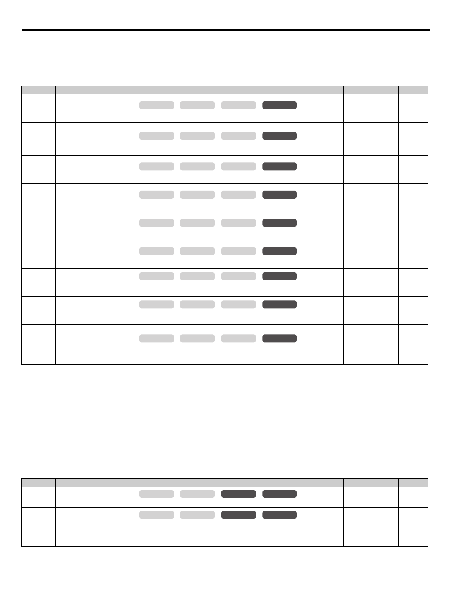
E5: PM Motor Settings
◆ F: Option Settings
F parameters are used to program the drive for Encoder and PG feedback from the motor and to function with option
cards.
■
F1: PG Speed Control Card
<4> Default setting value is dependent on the drive model (o2-04).
<10> The display resolution depends on the rated output power of the drive. Models 2A0018 to 2A0041 and 4A0009 to 4A0023 display values in
0.01 A units, while models 2A0059 to 2A0432 and 4A0030 to 4A0260 display values in 0.1 A units.
No.(Addr.)
Name
Description
Setting
Page
E5-02
(32AH)
<1> Parameter setting value is not reset to the default value when the drive is initialized.
<2> Default setting value is determined by the drive model (o2-04).
<3> The display resolution depends on the rated output power of the drive. Models 2A0018 to 2A0041 and 4A0009 to 4A0023 display values in
0.01 A units, while models 2A0059 to 2A0432 and 4A0030 to 4A0260 display values in 0.1 A units.
<4> Maximum setting is 48 when PG-E3 option is connected.
Motor Rated Power
Sets the rated capacity of the motor.
Default:
Min: 0.10 kW
Max: 650.00 kW
E5-03
(32BH)
Motor Rated Current
Sets the motor rated current.
Default:
Min: 10% of drive rated
current
Max: 200% of drive
rated current
E5-04
(32CH)
Number of Motor Poles
Sets the number of motor poles.
Default: 12
Min: 2
Max: 120
E5-05
(32DH)
Motor Stator Resistance
(Single Phase)
Sets the stator resistance (1 phase value).
Default:
Min: 0.000
Ω
Max: 65.000
Ω
E5-06
(32EH)
Motor d-Axis Inductance
Sets the d-axis inductance.
Default:
Min: 0.00 mH
Max: 600.00 mH
E5-07
(32FH)
Motor q-Axis Inductance
Sets the q-axis inductance.
Default:
Min: 0.00 mH
Max: 600.00 mH
E5-09
(331H)
Motor Induction Voltage Constant 1
Sets the induced phase peak voltage in units of 0.1 mV (rad/s) [electrical angle].
When setting this parameter, E5-24 should be set to 0.0.
Default:
Min: 0.0 mV/(rad/s)
Max:
6500.0 mV/(rad/s)
E5-11
(333H)
Encoder Offset
Sets the offset between the rotor magnetic axis and the encoder zero position. Set during
Encoder Offset Tuning.
Default: 0.0 deg
Min: -180 deg
Max: 180 deg
E5-24
(353H)
Motor Induction Voltage Constant 2
Sets the induced phase-to-phase rms voltage in units of 0.1 mV/(r/min) [mechanical angle].
When setting this parameter, E5-09 should be set to 0.0.
Default:
0.0 mV/(r/min)
Min:
0.0 mV/(r/min)
Max:
6500.0 mV/(r/min)
No.(Addr.)
Name
Description
Setting
Page
F1-01
(380H)
Encoder 1 Resolution
Sets the encoder resolution (number of pulses per revolution)
Default:
Min: 1 ppr
Max: 60000 ppr
F1-02
(381H)
Operation Selection at PG Open
Circuit (PGo)
0: Ramp to stop. Decelerate to stop using the deceleration ramp in C1-02.
1: Coast to stop.
2: Fast Stop. Decelerate to stop using the deceleration ramp in C1-09.
3: Alarm only.
Default: 1
Min: 0
Max: 3
common
_
CLV
CLV/PM
V/f
OLV
common
_
CLV
CLV/PM
V/f
OLV
common
_
CLV
CLV/PM
V/f
OLV
common
_
CLV
CLV/PM
V/f
OLV
common
_
CLV
CLV/PM
V/f
OLV
common
_
CLV
CLV/PM
V/f
OLV
common
_
CLV
CLV/PM
V/f
OLV
common
_
CLV
CLV/PM
V/f
OLV
common
_
CLV
CLV/PM
V/f
OLV
common
_
CLV
CLV/PM
V/f
OLV
common
_
CLV
CLV/PM
V/f
OLV