L4: speed detection, L3-02: stall prevention level during acceleration, L3-05: stall prevention selection during run – Yaskawa L1000E AC Drive Technical Manual for CIMR-LE Models for Elevator Applications User Manual
Page 219: L3-06: stall prevention level during run, 8 l: protection functions
5.8 L: Protection Functions
YASKAWA ELECTRIC SIEP YAIL1E 01A YASKAWA AC Drive L1000E Technical Manual
219
P
a
ra
me
te
r De
ta
ils
5
■
L3-02: Stall Prevention Level during Acceleration
Sets the output current level at which the Stall Prevention during acceleration is activated.
• Lower L3-02 if stalling occurs when using a motor that is relatively small compared to the drive.
• Also set parameter L3-03 when operating the motor in the constant power range.
■
L3-05: Stall Prevention Selection during Run
Determines how Stall Prevention works during Run. Stall Prevention during run prevents the motor from stalling by
automatically reducing the speed when a transient overload occurs while the motor is running at constant speed.
Note: 1. This function is available in V/f control mode.
2. Stall Prevention during run is disabled when the output frequency is 6 Hz or lower regardless of the L3-05 and L3-06 settings.
Setting 0: Disabled
Drive runs at the set speed reference. A heavy load may cause the motor to stall and trip the drive with an oC or oL fault.
Setting 1: Decelerate using C1-02
If the current exceeds the Stall Prevention level set in parameter L3-06, then the drive will decelerate at decel ramp 1 (C1-
02). Once the current level drops below the value of L3-06 minus 2% for 100 ms, the drive accelerates back to the speed
reference at the active acceleration ramp.
Setting 2: Decelerate using C1-04
Same as setting 1 except the drive decelerates at decel ramp 2 (C1-04).
■
L3-06: Stall Prevention Level during Run
Sets the Stall Prevention level during run as a percentage of the drive rate output current.
◆ L4: Speed Detection
These parameters set up the speed agree and speed detection functions which can be assigned to the multi-function output
terminals.
■
L4-01, L4-02: Speed Agreement Detection Level and Detection Width
Parameter L4-01 sets the detection level for the digital output functions “User-set speed agree 1,” “Speed detection 1,”
and “Speed detection 2.”
Parameter L4-02 sets the hysteresis level for these functions.
details on settings 2, 3, 4, and 5.
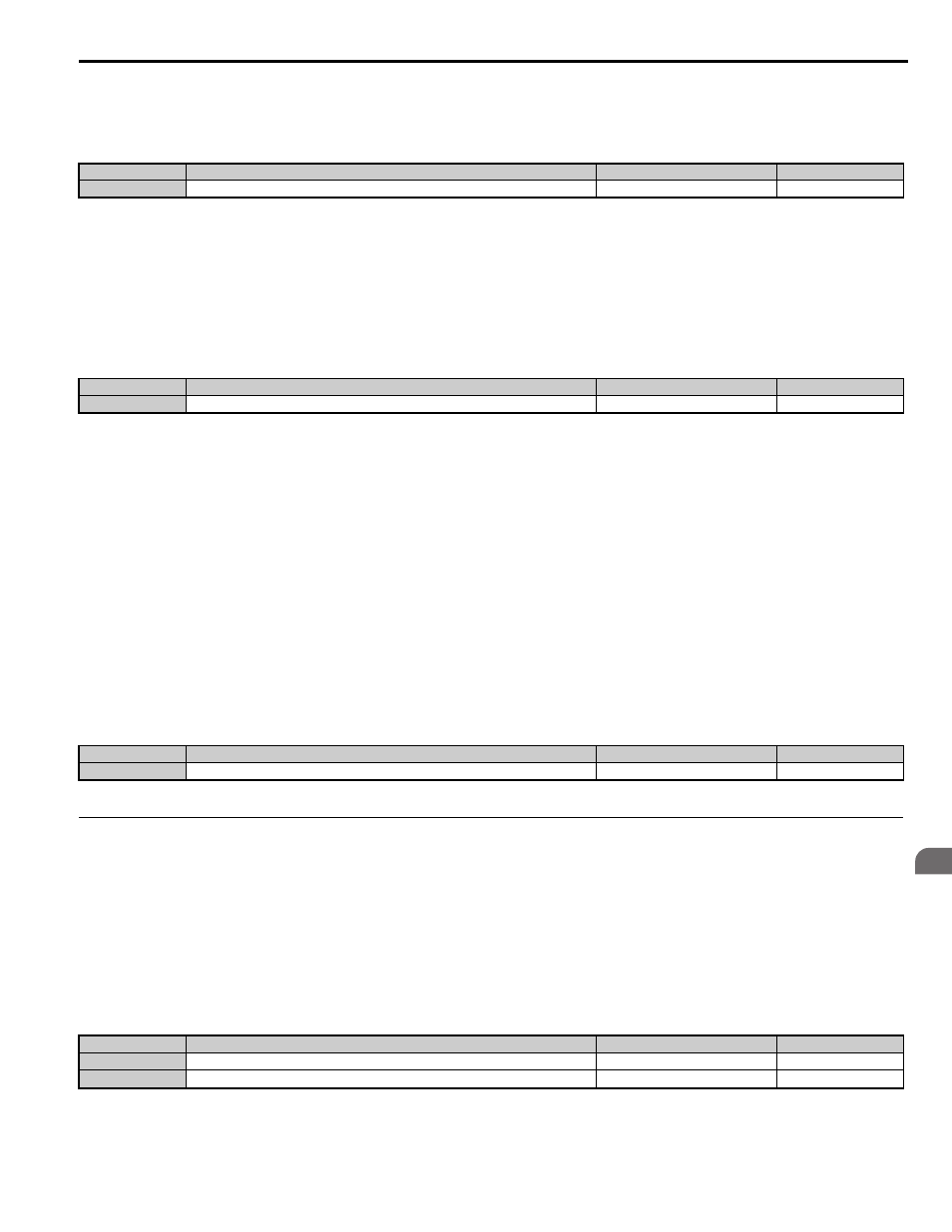
No.
<1> The upper limit and default value are determined by the carrier frequency reduction (L8-38).
Parameter Name
Setting Range
Default
L3-02
Stall Prevention Level during Acceleration
0 to 150%
No.
Parameter Name
Setting Range
Default
L3-05
Stall Prevention Selection during Run
0 to 2
1
No.
<1> The upper limit and default for this setting is determined by L8-38.
Parameter Name
Setting Range
Default
L3-06
Stall Prevention Level during Run
30 to 150%
No.
Parameter Name
Setting Range
Default
L4-01
Speed Agreement Detection Level
0.0 to 100.0%
0.0%
L4-02
Speed Agreement Detection Width
0.0 to 40.0%
4.0%