B1-06: digital input reading, B1-14: phase order selection, 2 b: application – Yaskawa L1000E AC Drive Technical Manual for CIMR-LE Models for Elevator Applications User Manual
Page 158: Defines how the digital inputs are read
5.2 b: Application
158
YASKAWA ELECTRIC SIEP YAIL1E 01A YASKAWA AC Drive L1000E Technical Manual
■
b1-06: Digital Input Reading
Defines how the digital inputs are read.
Setting 0: Read once
The state of a digital input is read once. If the state has changed, the input command is immediately processed. With this
setting the drive responds more quickly to digital inputs, but a noisy signal could cause erroneous operation.
Setting 1: Read twice
The state of a digital input is read twice. The input command is processed only if the state does not change during the
double reading. This reading process is slower than the “Read once” process, but it is more resistant to noisy signals.
■
b1-08: Up/Down Command Selection while in Programming Mode
As a safety precaution, the drive will not normally respond to an Up/Down command input when the digital operator is
being used to adjust parameters in the Programming Mode (Verify Menu, Setup Mode, Parameter Settings Mode, and
Auto-Tuning Mode). If required by the application, set b1-08 to allow the drive to run while in the Programming Mode.
Setting 0: Disabled
An Up/Down command is not accepted while the digital operator is in the Programming Mode.
Setting 1: Enabled
An Up/Down command is accepted in any digital operator mode.
Setting 2: Prohibit programming during run
It is not possible to enter the Programming Mode as long as the drive output is active. The Programming Mode cannot be
displayed during Run.
■
b1-14: Phase Order Selection
Sets the phase order for drive output terminals U/T1, V/T2, and W/T3. Switching motor phases will reverse the direction
of the motor. Use this parameter to switch the direction of the Up and Down commands.
Setting 0: Standard phase order (U-V-W)
Setting 1: Switched phase order (U-W-V)
Note: 1. If using a closed loop control mode such as CLV (A1-02 = 3) or CLV/PM (A1-02 = 7) and parameter b1-14 is changed, be sure to also
change the direction of the motor encoder (F1-05) to match the direction of the Up and Down commands.
2. If CLV/PM is used, also perform encoder offset Auto-Tuning.
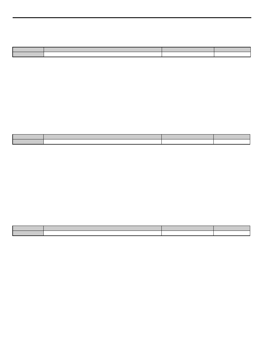
No.
Parameter Name
Setting Range
Default
b1-06
Digital Input Reading
0 or 1
1
No.
Parameter Name
Setting Range
Default
b1-08
Up/Down command Selection while in Programming Mode
0 to 2
0
No.
Parameter Name
Setting Range
Default
b1-14
Phase Order Selection
0 or 1
0