7 main circuit wiring, Main circuit terminal functions, Wire gauges and tightening torque – Yaskawa L1000E AC Drive Technical Manual for CIMR-LE Models for Elevator Applications User Manual
Page 64
64
YASKAWA ELECTRIC SIEP YAIL1E 01A YASKAWA AC Drive L1000E Technical Manual
3.7 Main Circuit Wiring
3.7 Main Circuit Wiring
This section describes the functions, specifications, and procedures required to safely and properly wire the main circuit
in the drive.
NOTICE: Only connect recommended devices to the drives braking transistor terminals. Failure to comply could result in damage to
the drive or braking circuit. Carefully review instruction manual TOBP C720600 00 when connecting a braking option to the drive.
NOTICE: Do not use the negative DC bus terminal “-” as a ground terminal. This terminal is at high DC voltage potential.
Improper wiring connections could damage the drive.
NOTICE: Equipment Hazard. Comply with proper wiring practices. The motor may run in reverse if the phase order is backward,
causing incorrect elevator direction movement. Connect motor input terminals U, V and W to drive output terminals U/T1,V/T2, and W/
T3. The phase order for the drive and motor should match.
Note: Do not solder the ends of wire connections to the drive. Soldered wiring connections can loosen over time. Improper wiring
practices could result in drive malfunction due to loose terminal connections.
NOTICE: Do not switch the drive input to start or stop the motor. Frequently switching the drive on and off shortens the life of the DC
bus charge circuit and the DC bus capacitors, and can cause premature drive failures. For the full performance life, refrain from
switching the drive on and off more than once every 30 minutes.
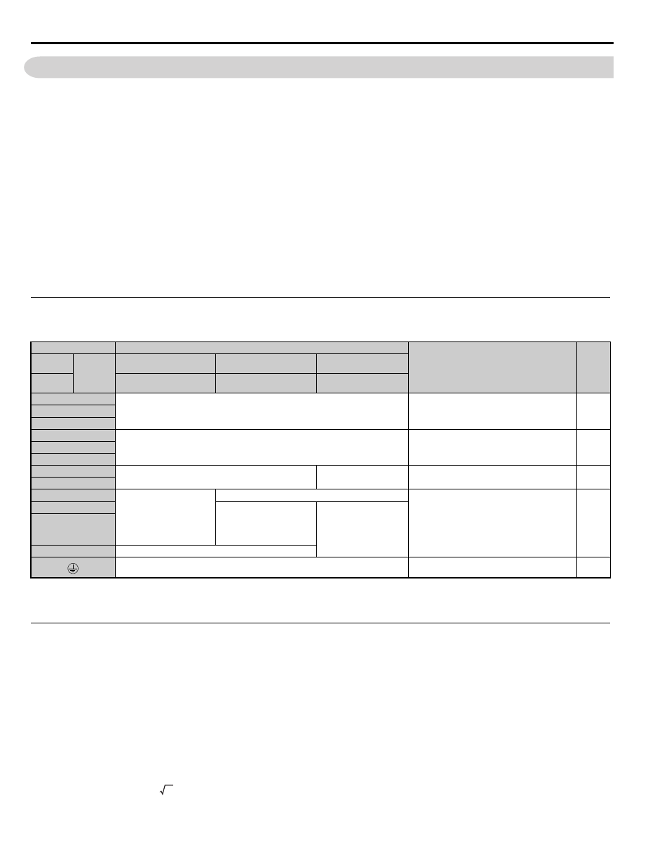
◆ Main Circuit Terminal Functions
Table 3.1 Main Circuit Terminal Functions
Note: Use terminal B1 and - when installing the braking unit (CDBR type) to the drives with built-in braking transistor (2A0018 to
2A0144, 4A0009 to 4A0075).
◆ Wire Gauges and Tightening Torque
Use the tables in this section to select the appropriate wires and crimp terminals.
Gauges listed in the tables are for use in the United States.
Note: 1. Wire gauge recommendations based on drive continuous current ratings using 75°C 600 Vac vinyl-sheathed wire assuming ambient
temperature within 40°C and wiring distance less than 100 m (328 ft.).
2. Terminals B1, B2, +1, +2, and +3, are for connecting a DC link choke, braking resistor or DC power supply. Do not connect other
nonspecific devices to these terminals.
• Consider the amount of voltage drop when selecting wire gauges. Increase the wire gauge when the voltage drop is
greater than 2% of motor rated voltage. Ensure the wire gauge is suitable for the terminal block. Use the following
formula to calculate the amount of voltage drop:
Line drop voltage (V) =
× wire resistance (Ω/km) × wire length (m) × current (A) × 10
-3
Terminal
Type
Function
Page
200 V
Class
Drive
Model
2A0018 to 2A0094
2A0106, 2A0144
2A0181 to 2A0432
400 V
Class
4A0009 to 4A0049
4A0056, 4A0075
4A0094 to 4A0260
R/L1
Main circuit power supply input
Connects line power to the drive
S/L2
T/L3
U/T1
Drive output
Connects to the motor
V/T2
W/T3
B1
Braking resistor
Not available
Available for connecting a braking resistor or a
braking resistor unit option
B2
+2
• DC link choke connection
(+1, +2) (remove the
shorting bar between +1 and
+2)
• DC power supply input
(+1, –)
not available
For connection
• of the drive to a DC power supply (terminals +1
and – are not UL approved)
• of dynamic braking options
+1
• DC power supply input
(+1, –)
• DC power supply input
(+1, –)
• Braking unit connection
(+3, –)
–
+3
not available
For 200 V class: 100
Ω or less
For 400 V class: 10
Ω or less
Grounding terminal
3