Output-side noise filter, Y e a _tm only, 5 installing peripheral devices – Yaskawa L1000E AC Drive Technical Manual for CIMR-LE Models for Elevator Applications User Manual
Page 353
8.5 Installing Peripheral Devices
YASKAWA ELECTRIC SIEP YAIL1E 01A YASKAWA AC Drive L1000E Technical Manual
353
Per
iphe
ra
l De
vi
ce
s &
Optio
n
s
8
■
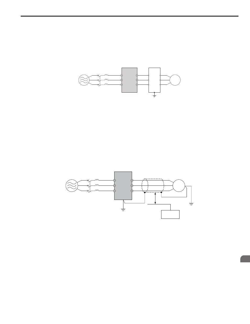
Output-Side Noise Filter
A noise filter on the output side of the drive reduces inductive noise and radiated noise.
illustrates an
example of output-side noise filter wiring.
NOTICE: Do not connect phase-advancing capacitors or LC/RC noise filters to the output circuits. Improper application of noise filters
could result in damage to the drive.
Figure 8.21
Figure 8.23 Output-Side Noise Filter
• Radiated Noise: Electromagnetic waves radiated from the drive and cables create noise throughout the radio
bandwidth that can affect surrounding devices.
• Induced Noise: Noise generated by electromagnetic induction can affect the signal line and may cause the controller to
malfunction.
Preventing Induced Noise
Use a noise filter on the output side or use shielded cables. Lay the cables at least 30 cm away from the signal line to
prevent induced noise.
Figure 8.22
Figure 8.24 Preventing Induced Noise
A – Power supply
C – Output-side noise filter
B – Drive
D – Motor
A – Power supply
E – Separate at least 30 cm
B – Drive
F – Controller
C – Shielded motor cable
G – Signal line
D – Motor
C
D
B
A
M
R/L1
MCCB
S/L2
T/L3
U/T1
V/T2
W/T3
1
2
3
4
5
6
Y E A
_TM
only
B
A
C
F
G
E
R/L1
MCCB
S/L2
T/L3
U/T1
V/T2
W/T3
D
M
Y E A
_TM
only