S: elevator parameters, O4: maintenance monitor settings, S1: brake sequence – Yaskawa L1000E AC Drive Technical Manual for CIMR-LE Models for Elevator Applications User Manual
Page 397: B.3 parameter table
B.3 Parameter Table
YASKAWA ELECTRIC SIEP YAIL1E 01A YASKAWA AC Drive L1000E Technical Manual
397
Pa
ra
met
er
L
is
t
B
■
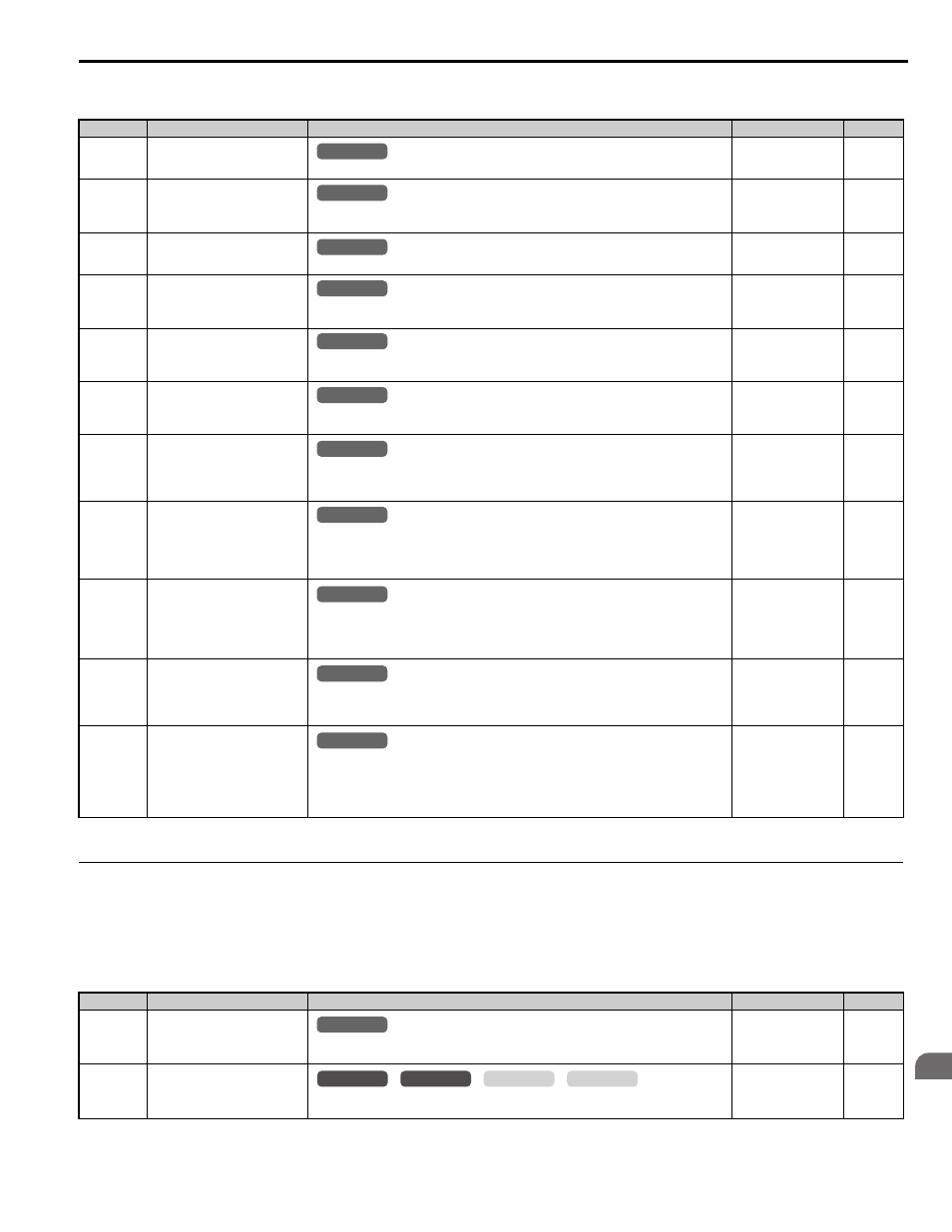
o4: Maintenance Monitor Settings
◆ S: Elevator Parameters
This section describes various functions and faults needed to operate an elevator application: braking sequence, slip
compensation for elevators, start/stop optimization, Rescue Operation, and elevator-related faults.
■
S1: Brake Sequence
No. (Addr.)
Name
Description
Setting
Page
o4-01
(50BH)
<1> Parameter setting value is not reset to the default value during drive initialization (A1-03).
Cumulative Operation Time
Setting
Sets the value for the cumulative operation time of the drive in units of 10 h.
Default: 0
Min: 0
Max: 9999
o4-02
(50CH)
Cumulative Operation Time
Selection
0: Logs power-on time
1: Logs operation time when the drive output is active (output operation time).
Default: 0
Min: 0
Max: 1
o4-03
(50EH)
Cooling Fan Operation Time
Setting
Sets the value of the fan operation time monitor U4-03 in units of 10 h.
Default: 0 h
Min: 0 h
Max: 9999 h
o4-05
(51DH)
Capacitor Maintenance Setting
Sets the value of the Maintenance Monitor for the capacitors. See U4-05 to check when the
capacitors may need to be replaced.
Default: 0%
Min: 0%
Max: 150%
o4-07
(523H)
DC bus Pre-charge Relay
Maintenance Setting
Sets the value of the Maintenance Monitor for the soft charge bypass relay. See U4-06 to check
when the bypass relay may need to be replaced.
Default: 0%
Min: 0%
Max: 150%
o4-09
(525H)
IGBT Maintenance Setting
Sets the value of the Maintenance Monitor for the IGBTs. See U4-07 to check when the IGBTs
may need to be replaced.
Default: 0%
Min: 0%
Max: 150%
o4-11
(510H)
U2, U3 Initialization
0: U2- and U3- monitor data is not reset when the drive is initialized (A1-03).
1: Resets the data for the U2- and U3- monitors. Once o4-11 is set to 1 and the ENTER
key is pressed, fault data is erased and the display returns to 0.
Default: 0
Min: 0
Max: 1
o4-12
(512H)
kWh Monitor Initialization
0: U4-10 and U4-11 monitor data is not reset when the drive is initialized (A1-03).
1: Resets the kWh counter. The monitors U4-10 and U4-11 will display "0" after they are
initialized. Once o4-12 is set to 1 and the ENTER key is pressed, kWh data is erased and the
display returns to 0.
Default: 0
Min: 0
Max: 1
o4-13
(528H)
Number of Travels Counter Reset
0: Keep the number of travels counter value. The counter is not reset when the drive is
initialized (A1-03).
1: Resets the number 0 travels counter. The monitor U4-24/25 will show 0. Once o4-13 is set to
1 and the ENTER key is pressed, the counter value is erased and the display returns to 0.
Default: 0
Min: 0
Max: 1
o4-15
(537H)
Maintenance Alarm Snooze Period After a maintenance alarm output has been triggered, o4-15 determines the level that will
trigger the next alarm for the same component. The same alarm will be triggered by the
detection level that triggered the original alarm plus the level set in o4-15.
Default: 2%
Min: 0%
Max: 20%
o4-16
(176H)
Maintenance Monitoring Selection
Selects the Maintenance Monitor using bits 0 to 3.
0: LT1 (cooling fan)
1: LT2 (DC bus capacitors)
2: LT3 (soft-charge bypass relay)
3: LT4 (IGBTs have passed 90% of the their life expectancy)
Default: 1000
Min: 0000
Max: 1111
No. (Addr.)
Name
Description
Setting
Page
S1-01
(680H)
Zero Speed Level at Stop
Determines the speed to begin applying DC Injection (or Position Lock) when the drive is
ramping to stop (b1-03 = 0). Set as a percentage of the maximum output frequency (E1-04).
Default:
Min: 0.000%
Max: 9.999%
S1-02
(681H)
DC Injection Current at Start
Determines the amount of current to use for DC Injection at start. Set as a percentage of the
drive rated current.
Default: 50%
Min: 0%
Max: 100%
All Modes
common
_
All Modes
common
_
All Modes
common
_
All Modes
common
_
All Modes
common
_
All Modes
common
_
All Modes
common
_
All Modes
common
_
All Modes
common
_
All Modes
common
_
All Modes
common
_
All Modes
common
_
common
_
CLV
CLV/PM
V/f
OLV