Terminal functions of pg-b3 and pg-x3 option, Table 8.9, Block, refer to – Yaskawa L1000E AC Drive Technical Manual for CIMR-LE Models for Elevator Applications User Manual
Page 346: Crimp terminals, 4 option card installation, Table 8.8 crimp terminal sizes
8.4 Option Card Installation
346
YASKAWA ELECTRIC SIEP YAIL1E 01A YASKAWA AC Drive L1000E Technical Manual
■
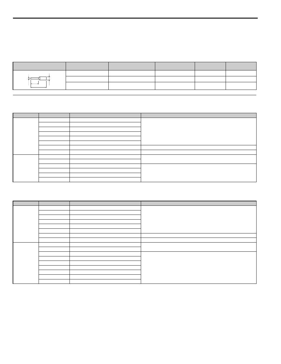
Crimp Terminals
Yaskawa recommends using CRIMPFOX 6 by Phoenix Contact or equivalent crimp terminals with the specifications
listed in
for wiring to ensure proper connections.
Note: Properly trim wire ends so loose wire ends do not extend from the crimp terminals.
Table 8.8 Crimp Terminal Sizes
◆ Terminal Functions of PG-B3 and PG-X3 Option
Table 8.9 PG-B3 Option Terminal Functions
Table 8.10 PG-X3 Option Terminal Functions
Wire Gauge
mm
2
Phoenix Contact Model
L
mm (in)
d1
mm (in)
d2
mm (in)
0.25 (24 AWG)
AI 0.25 - 6YE
10.5 (13/32)
0.8 (1/32)
2 (5/64)
0.34 (22 AWG)
AI 0.34 - 6TQ
10.5 (13/32)
0.8 (1/32)
2 (5/64)
0.5 (20 AWG)
AI 0.5 - 6WH
14 (9/16)
1.1 (3/64)
2.5 (3/32)
Terminal Block
Terminal
Function
Description
TB1
<1> A separate UL-listed class 2 power supply is necessary when the PG requires more than 200 mA to operate.
A+
A+ pulse signal input
• Pulse signal inputs from the PG.
• Signal inputs from complementary and open-collector outputs
• Signal level
H level: 8 to 12 V
L level: 2.0 V or less
A–
A– pulse signal input
B+
B+ pulse signal input
B–
B– pulse signal input
Z+
Z+ pulse signal input
Z–
Z– pulse signal input
SD
NC pin (open)
For use when cables shields should not be grounded
FE
Ground
Used for grounding shielded lines
TB2
IP
PG power supply
• Output voltage: 12.0 V ± 5%
• Max output current: 200 mA
IG
PG power supply common
AO
A pulse monitor signal
• Outputs the monitor signal for the A, B, and Z pulses from the PG speed control card
• For open collector outputs from the option
• Max voltage: 24 V
• Max current: 30 mA
BO
B pulse monitor signal
ZO
Z pulse monitor signal
IG
Monitor signal common
Terminal Block
Terminal
Function
Description
TB1
<1> A separate UL-listed class 2 power supply is necessary when the PG requires more than 200 mA to operate.
A+
A+ pulse signal input
• Inputs for the A channel, B channel, and Z pulses from the PG encoder
• Signal level matches RS-422
A–
A– pulse signal input
B+
B+ pulse signal input
B–
B– pulse signal input
Z+
Z+ pulse signal input
Z–
Z– pulse signal input
SD
NC pin (open)
Open connection connectors for use when cable shields should not be grounded
FE
Ground
Used as the shield ground termination point.
TB2
IP
PG encoder power supply
• Output voltage: 12.0 V ± 5% or 5.5 V ± 5%
• Max. output current: 200 mA
IG
PG encoder power supply common
SG
Monitor signal common
• Output signal for monitoring A channel, B channel, and Z pulses from the PG encoder
• Signal level matches RS-422
a+
A+ pulse monitor signal
a–
A- pulse monitor signal
b+
B+ pulse monitor signal
b–
B- pulse monitor signal
z+
Z+ pulse monitor signal
z–
Z- pulse monitor signal
d1
d2
6 mm
L