Alarm and error displays, Faults, 2 drive alarms, faults, and errors – Yaskawa L1000E AC Drive Technical Manual for CIMR-LE Models for Elevator Applications User Manual
Page 271: Table 6.2 fault displays (1)
6.2 Drive Alarms, Faults, and Errors
YASKAWA ELECTRIC SIEP YAIL1E 01A YASKAWA AC Drive L1000E Technical Manual
271
T
ro
ubles
hoo
ting
6
◆ Alarm and Error Displays
■
Faults
gives an overview of possible fault codes. Conditions such as overvoltages can trip faults and alarms. It is
important to distinguish between faults and alarms to determine the proper corrective actions.
When the drive detects a fault, the ALM indicator LED lights, the fault code appears on the digital operator, and the fault
contact MA-MB-MC triggers. An alarm is present if the ALM LED blinks and the fault code on the digital operator
flashes. Refer to
Minor Faults and Alarms on page 272
for a list of alarm codes.
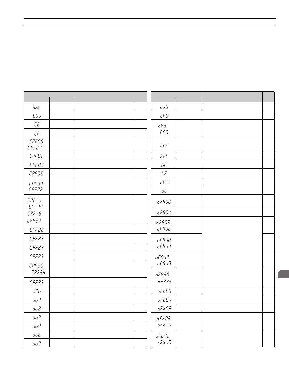
Table 6.2 Fault Displays (1)
Digital Operator Display
Name
Page
Digital Operator Display
Name
Page
LED Operator
LCD Operator
LED Operator
LCD Operator
boL
Braking Transistor Overload
dv8
PM Rotor Position Estimation Error
bUS
Option Communication Error
EF0
Option Card External Fault
CE
MEMOBUS/Modbus Communication
Error
to
EF3 to EF8
External Fault (input terminal S3 to S8)
CF
Control Fault
,
CPF00, CPF01
Control Circuit Error
Err
EEPROM Write Error
CPF02
A/D Conversion Error
FrL
Speed Reference Missing
CPF03
Control Board Connection Error
GF
Ground Fault
CPF06
EEPROM Data Error
LF
Output Phase Loss
,
CPF07,
CPF08
Terminal Board Connection Error
LF2
Output Current Imbalance
oC
Overcurrent
to
,
to
CPF11 to CPF14,
CPF16 to CPF21
Control Circuit Error
oFA00
Option Card Connection Error at Option
Connector CN5-A, Option Card Fault at
Option Connector CN5-A
oFA01
Option Card Fault at Option Connector
CN5-A
,
oFA05, oFA06
Option Card Error Occurred at Option Port
CN5-A
CPF22
Hybrid IC Failure
CPF23
Control Board Connection Error
,
oFA10, oFA11
CPF24
Drive Unit Signal Fault
CPF25
Terminal Board not Connected
to
oFA12 to oFA17
to
CPF26 to CPF34 Control Circuit Error
to
oFA30 to oFA43
CPF35
A/D Conversion Error
dEv
Speed Deviation (for Control Mode with
Encoder)
oFb00
Option Card Connection Error (CN5-B)
dv1
Encoder Z Pulse Fault
oFb01
Option Card Fault (CN5-B)
dv2
Z Pulse Noise Fault Detection
oFb02
Option Card Fault (CN5-B)
dv3
Inversion Detection
,
oFb03, oFb11
Option Card Error (CN5-B)
dv4
Inversion Prevention Detection
dv6
Overacceleration Detection
to
oFb12 to oFb17
Option Card Connection Error (CN5-B)
dv7
Rotor Polarity Detection Timeover