L7: torque limit, L8: drive protection, B.3 parameter table – Yaskawa L1000E AC Drive Technical Manual for CIMR-LE Models for Elevator Applications User Manual
Page 391
B.3 Parameter Table
YASKAWA ELECTRIC SIEP YAIL1E 01A YASKAWA AC Drive L1000E Technical Manual
391
Pa
ra
met
er
L
is
t
B
■
L7: Torque Limit
■
L8: Drive Protection
L6-04
(4A4H)
Torque Detection Selection 2
0: Disabled
1: oL4 detection only active during speed agree, operation continues after detection
2: oL4 detection always active during run, operation continues after detection
3: oL4 detection only active during speed agree, output shuts down on an oL4 fault
4: oL4 detection always active during run, output shuts down on an oL4 fault
5: UL4 detection only active during speed agree, operation continues after detection
6: UL4 detection always active during run, operation continues after detection
7: UL4 detection only active during speed agree, output shuts down on an oL4 fault
8: UL4 detection always active during run, output shuts down on an oL4 fault
Default: 0
Min: 0
Max: 8
L6-05
(4A5H)
Torque Detection Level 2
Sets the overtorque and undertorque detection level.
Default: 150%
Min: 0%
Max: 300%
L6-06
(4A6H)
Torque Detection Time 2
Sets the time an overtorque or undertorque condition must exist to trigger torque detection 2.
Default: 0.1 s
Min: 0.0 s
Max: 10.0 s
No. (Addr.)
Name
Description
Setting
Page
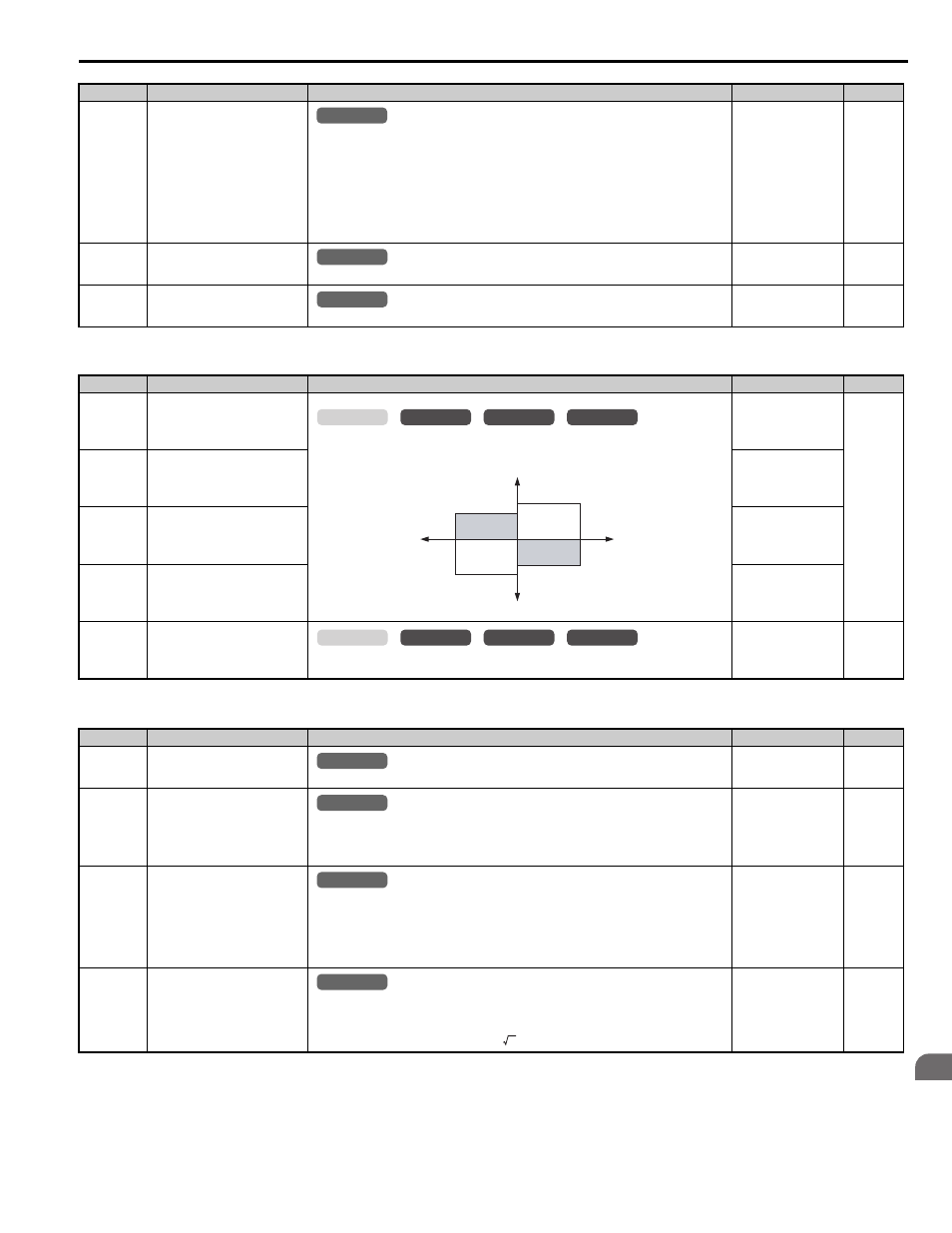
L7-01
(4A7H)
Forward Torque Limit
Sets the torque limit value as a percentage of the motor rated torque. Four individual quadrants
can be set.
Default: 200%
Min: 0%
Max: 300%
L7-02
(4A8H)
Reverse Torque Limit
Default: 200%
Min: 0%
Max: 300%
L7-03
(4A9H)
Forward Regenerative Torque
Limit
Default: 200%
Min: 0%
Max: 300%
L7-04
(4AAH)
Reverse Regenerative Torque
Limit
Default: 200%
Min: 0%
Max: 300%
L7-16
(44DH)
Torque Limit Process at Start
0: Disabled
1: Enabled
Default: 1
Min: 0
Max: 1
No. (Addr.)
Name
Description
Setting
Page
L8-02
(4AEH)
Overheat Alarm Level
An overheat alarm will occur if the heatsink temperature exceeds the level set in L8-02.
Default:
Min: 50
°C
Max: 150
°C
L8-03
(4AFH)
Overheat Pre-Alarm Operation
Selection
0: Ramp to stop. A fault is triggered.
1: Coast to stop. A fault is triggered.
2: Fast Stop. Decelerate to stop using the deceleration ramp in C1-09. A fault is triggered.
3: Continue operation. An alarm is triggered.
Default: 3
Min: 0
Max: 3
L8-05
(4B1H)
Input Phase Loss Protection
Selection
Selects the detection of input current phase loss, power supply voltage imbalance, or main
circuit electrolytic capacitor deterioration.
0: Disabled
1: Enabled always
2: Enabled during operation
3: Enabled during constant speed
Default: 1
Min: 0
Max: 3
L8-06
(4B2H)
Input Phase Loss Detection Level
When ripple is observed in the DC bus, expansion of the input bias is calculated and becomes
the input phase if the difference between the max and minimum values of the ripple are greater
than L8-06.
Detection Level = 100% = Voltage class
×
(determines standards for setting values)
Default:
Min: 0.0%
Max: 50.0%
No. (Addr.)
Name
Description
Setting
Page
All Modes
common
_
All Modes
common
_
All Modes
common
_
common
_
CLV
CLV/PM
V/f
OLV
L7-01
L7-03
L7-02
L7-04
Output Torque
Positive Torque
REV
Negative Torque
FWD
Motor
r/min
Regeneration
Regeneration
common
_
CLV
CLV/PM
V/f
OLV
All Modes
common
_
All Modes
common
_
All Modes
common
_
All Modes
common
_
2