Refer to wire gauges, tightening, 4 option card installation – Yaskawa L1000E AC Drive Technical Manual for CIMR-LE Models for Elevator Applications User Manual
Page 345
8.4 Option Card Installation
YASKAWA ELECTRIC SIEP YAIL1E 01A YASKAWA AC Drive L1000E Technical Manual
345
Per
iphe
ra
l De
vi
ce
s &
Optio
n
s
8
9.
For the PG-B3 and PG-X3 Option, set drive parameters
A1-02: Control Method Selection on page 151
and
PG Speed Control Card on page 378
for proper motor rotation.
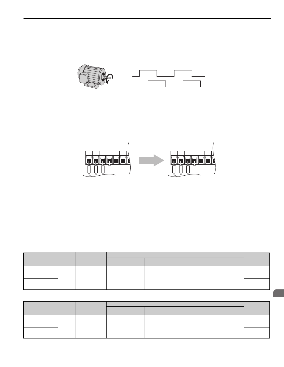
With a two-pulse or three-pulse PG encoder, the leading pulse determines the motor rotation direction. A PG
encoder signal with leading A pulse is considered to be rotating forward (counter-clockwise when viewing rotation
from motor load side).
Figure 8.11
Figure 8.13 Displacement of A and B Pulses
10.
After connecting the PG encoder outputs to the option, apply power to the drive and manually rotate the motor
and check the rotation direction by viewing monitor U1-05 on the digital operator.
Reverse motor rotation is indicated by a negative value for U1-05; forward motor rotation is indicated by a
positive value.
If monitor U1-05 indicates that the forward direction is opposite of what is intended, set F1-05 to 1, or reverse the
two A pulse wires with the two B pulse wires on option terminal TB1 as shown in
Figure 8.12
Figure 8.14 A Channel and B Channel Wire Switching
11.
If switching the wires is inconvenient, set drive parameter F1-05 to 1 to switch the direction of how the option
reads pulses from the PG encoder output.
Please note that when the drive is initialized using A1-03 =1110, 2220, 3330, the value for F1-05 will reset to
factory default and the parameter will need to be adjusted again to switch the direction.
◆ Wire Gauges, Tightening Torque, and Crimp Terminals
■
Wire Gauges and Tightening Torques of PG-B3 and PG-X3 Option
Wire gauge and torque specifications are listed in
.
Table 8.6 Wire Gauges and Tightening Torques of PG-B3 Option
Table 8.7 Wire Gauges and Tightening Torques of PG-X3 Option
Terminal Signal
Screw
Size
Tightening Torque
N"m
(in"lb)
Bare Cable
Crimp Terminals
Wire Type
Applicable Gauges
mm
2
Recomm. Gauge
mm
2
Applicable Gauges
mm
2
Recomm. Gauge
mm
2
A+, A–, B+,
B–, Z+, Z–,
FE, IP, IG
M2
0.22 to 0.25
(1.95 to 2.21)
Stranded wire:
0.25 to 1.0
(24 to 17 AWG)
Solid wire:
0.25 to 1.5
(24 to 16 AWG)
0.75
(18 AWG)
0.25 to 0.5
(24 to 20 AWG)
0.5
(20 AWG)
Shielded twisted
pair, etc.
AO, IG, BO,
IG, ZO, IG
Shielded cable,
etc.
Terminal Signal
Screw
Size
Tightening Torque
N"m
(in"lb)
Bare Cable
Crimp Terminals
Wire Type
Applicable Gauges
mm
2
Recomm. Gauge
mm
2
Applicable Gauges
mm
2
Recomm. Gauge
mm
2
A+, A–, B+,
B–, Z+, Z–,
SD, FE, IP, IG
M2
0.22 to 0.25
(1.95 to 2.21)
Stranded wire:
0.25 to 1.0
(24 to 17 AWG)
Solid wire:
0.25 to 1.5
(24 to 16 AWG)
0.75
(18 AWG)
0.25 to 0.5
(24 to 20 AWG)
0.5
(20 AWG)
Shielded twisted
pair, etc.
a+, a–, b+,
b–, z+, z–, SG
Shielded cable,
etc.
A pulse
B pulse
The A pulse leads, followed
by the B pulse displaced at 90 degrees
Time
→
A+ A- B+ B- Z+ Z-
3
4
5
6
A+ A- B+ B- Z+ Z-
5
6
3
4
B
3