B: application, B1: operation mode selection, B2: magnetic flux compensation – Yaskawa L1000E AC Drive Technical Manual for CIMR-LE Models for Elevator Applications User Manual
Page 369: B4: delay timers, B.3 parameter table
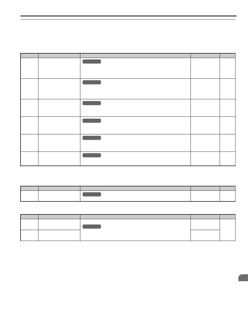
B.3 Parameter Table
YASKAWA ELECTRIC SIEP YAIL1E 01A YASKAWA AC Drive L1000E Technical Manual
369
Pa
ra
met
er
L
is
t
B
◆ b: Application
Application parameters configure the source of the Up/Down command, timer functions, the Dwell function, the Droop
Control function, Energy Savings, and a variety of other application-related settings.
■
b1: Operation Mode Selection
■
b2: Magnetic Flux Compensation
■
b4: Delay Timers
No.(Addr.)
Name
Description
Setting
Page
b1-01
(180H)
Speed Reference Selection
0: Digital operator
1: Analog input terminals
2: MEMOBUS/Modbus communications
3: Option card
Default: 0
Min: 0
Max: 3
b1-02
(181H)
Up/Down Command Selection
0: Digital operator
1: Digital input terminals
2: MEMOBUS/Modbus communications
3: Option card
Default: 1
Min: 0
Max: 3
b1-03
(182H)
<1> Maximum setting value is 1 in V/f Control and OLV Control.
Stopping Method Selection
0: Ramp to stop
1: Coast to stop
4: Elevator Emergency Stop
Default: 0
Min: 0
Max: 4
b1-06
(185H)
Digital Input Reading
0: Input status is read once and processed immediately (for quick response).
1: Input is read twice and processed only if the status is the same in both readings (robust
against noisy signals).
Default: 1
Min: 0
Max: 1
b1-08
(187H)
Up/Down Command Selection
while in Programming Mode
0: Up/Down command not accepted while in the Programming Mode.
1: Up/Down command accepted while in the Programming Mode.
2: Prohibit entering Programming Mode during run.
Default: 0
Min: 0
Max: 2
b1-14
(1C3H)
Phase Order Selection
0: U-V-W
1: U-W-V
Default: 0
Min: 0
Max: 1
No.(Addr.)
Name
Description
Setting
Page
b2-08
(190H)
Magnetic Flux Compensation
Value
Sets the magnetic flux compensation as a percentage of the no-load current value (E2-03).
Default: 0%
Min: 0%
Max: 1000%
No.(Addr.)
Name
Description
Setting
Page
b4-01
(1A3H)
Timer Function On-Delay Time
Used to set the on-delay and off-delay times for a digital timer output (H2-=12). The output
is triggered by a digital input programmed to H1-=18.
Default: 0.0 s
Min: 0.0 s
Max: 3000.0 s
b4-02
(1A4H)
Timer Function Off-Delay Time
Default: 0.0 s
Min: 0.0 s
Max: 3000.0 s
All Modes
common
_
All Modes
common
_
All Modes
common
_
All Modes
common
_
All Modes
common
_
All Modes
common
_
common
_
All Modes
All Modes
common
_