E.3 user setting table – Yaskawa L1000E AC Drive Technical Manual for CIMR-LE Models for Elevator Applications User Manual
Page 467

E.3 User Setting Table
YASKAWA ELECTRIC SIEP YAIL1E 01A YASKAWA AC Drive L1000E Technical Manual
467
Qui
ck
Ref
er
enc
e Sh
eet
E
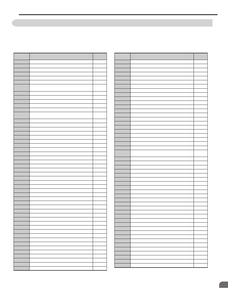
E.3 User Setting Table
Use the Verify Menu to see which parameters have been changed from their original default settings.
• The diamond next to the parameter number indicates that the parameter setting can be changed during run.
• Parameter names in boldface type are included in the Setup Group of parameters.
No.
Name
User
Setting
A1-00
Language Selection
A1-01
Access Level Selection
A1-02
Control Method Selection
A1-03
Initialize Parameters
A1-04
Password
A1-05
Password Setting
A2-01 to
A2-32
User Parameters, 1 to 32
A2-33
User Parameter Automatic Selection
b1-01
Speed Reference Selection
b1-02
Up/Down Command Selection
b1-03
Stopping Method Selection
b1-06
Digital Input Reading
b1-08
Up/Down Command Selection while in Programming
Mode
b1-14
Phase Order Selection
b2-08
Magnetic Flux Compensation Value
b4-01
Timer Function On-Delay Time
b4-02
Timer Function Off-Delay Time
b6-01
Dwell Speed at Start
b6-02
Dwell Time at Start
b6-03
Dwell Speed at Stop
b6-04
Dwell Time at Stop
b7-01
Droop Control Gain
b7-02
Droop Control Delay Time.
b8-01
Energy Saving Control Selection
b8-16
Energy Saving Control Constant (Ki)
b8-17
Energy Saving Control Constant (Kt)
C1-01
Acceleration Ramp 1
C1-02
Deceleration Ramp 1
C1-03
Acceleration Ramp 2
C1-04
Deceleration Ramp 2
C1-05
Acceleration Ramp 3 (Motor 2 Accel Time 1)
C1-06
Deceleration Ramp 3 (Motor 2 Decel Time 1)
C1-07
Acceleration Ramp 4 (Motor 2 Accel Time 2)
C1-08
Deceleration Ramp 4 (Motor 2 Decel Time 2)
C1-09 Fast
Stop
Ramp
C1-10
Accel/Decel Setting Resolution
C1-11
Accel/Decel Switching Speed
C1-12
Motor 2 Acceleration Time
C1-13
Motor 2 Deceleration Time
C1-15
Inspection Deceleration Ramp
C2-01
Jerk at Accel Start
C2-02
Jerk at Accel End
C2-03
Jerk at Decel Start
C2-04
Jerk at Decel End
C2-05
Jerk below Leveling Speed
C3-01
Slip Compensation Gain
C3-02
Slip Compensation Primary Delay Time
C3-03
Slip Compensation Limit
C3-04
Slip Compensation Selection during Regeneration
C3-05
Output Voltage Limit Operation Selection
No.
Name
User
Setting
C3-21
Motor 2 Slip Compensation Gain
C3-22
Motor 2 Slip Compensation Primary Delay Time
C3-23
Motor 2 Slip Compensation Limit
C3-24
Motor 2 Slip Compensation Selection during Regeneration
C4-01
Torque Compensation Gain
C4-02
Torque Compensation Primary Delay Time
C4-03
Torque Compensation at Forward Start
C4-04
Torque Compensation at Reverse Start
C4-05
Torque Compensation Time Constant
C4-07
Motor 2 Torque Compensation Gain
C5-01
Speed Control Loop Proportional Gain 1
C5-02
Speed Control Loop Integral Time 1
C5-03
Speed Control Loop Proportional Gain 2
C5-04
Speed Control Loop Integral Time 2
C5-06
Speed Control Loop Primary Delay Time Constant
C5-07
Speed Control Loop Settings Switching Speed
C5-08
Speed Control Loop Integral Limit
C5-13
Speed Control Loop Proportional Gain 3
C5-14
Speed Control Loop Integral Time 3
C5-16
Speed Control Loop Delay Time during Position Lock
C5-17
Motor Inertia
C5-18
Load Inertia Ratio
C5-19
Speed Control Loop Proportional Gain Time during
Position Lock
C5-20
Speed Control Loop Integral Time during Position Lock
C5-21
Motor 2 ASR Proportional Gain 1
C5-22
Motor 2 ASR Integral Time 1
C5-23
Motor 2 ASR Proportional Gain 2
C5-24
Motor 2 ASR Integral Time 2
C5-25
Motor 2 ASR Limit
C5-26
Motor 2 ASR Primary Delay Time Constant
C5-27
Motor 2 ASR Gain Switching Frequency
C5-28
Motor 2 ASR Integral Limit
C5-32
Integral Operation during Accel/Decel for Motor 2
C5-37
Motor 2 Inertia
C5-38
Motor 2 Load Inertia Ratio
C5-50
Set Vibrational Frequency
C6-03
Carrier Frequency
C6-06
PWM Method
C6-09
Carrier Frequency during Rotational Auto-Tuning
C6-21
Inspection Operation Carrier Frequency
C6-23
Carrier Frequency during Initial Motor Pole Search
C6-31
Carrier Frequency during Rescue Operation
d1-01
Speed Reference 1
d1-02
Speed Reference 2
d1-03
Speed Reference 3
d1-04
Speed Reference 4
d1-05
Speed Reference 5
d1-06
Speed Reference 6
d1-07
Speed Reference 7
d1-08
Speed Reference 8