Yaskawa L1000E AC Drive Technical Manual for CIMR-LE Models for Elevator Applications User Manual
Page 205

5.7 H: Terminal Functions
YASKAWA ELECTRIC SIEP YAIL1E 01A YASKAWA AC Drive L1000E Technical Manual
205
P
a
ra
me
te
r De
ta
ils
5
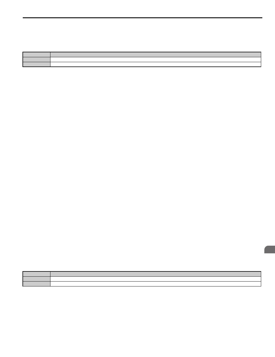
Setting 1C: Motor 2 selection
Indicates which motor is selected when another output terminal is set up to switch drive operation between two motors
(H1- = 16). Refer to
Setting 16: Motor 2 selection on page 195
for details on switching motors.
Setting 1D: During regeneration
Terminal closes when the motor is driven in the regenerative mode.
Setting 1E: Reset enabled
An output set for “Reset enabled” closes when the drive attempts to reset after a fault has occurred.
The fault reset function allows the drive to automatically clear a fault. The terminal set to 1E will close after the fault is
cleared and the drive has attempted to reset. If the drive cannot successfully reset within the number of attempts permitted
by L5-01, a fault will be triggered and the terminal set to 1E will open.
Refer to L5: Automatic Fault Reset on page 221
for details on automatic reset.
Setting 1F: Motor overload alarm (oL1)
The output closes when the motor overload level estimated by the oL1 fault detection exceeds 90% of the oL1 detection
level.
Setting 20: Drive overheat pre-alarm (oH)
Output closes whenever the drive heatsink temperature reaches the level specified by parameter L8-02.
Overheat Alarm Level on page 225
for details on drive overheat detection.
Setting 2F: Maintenance period
Output closes when the cooling fan, DC bus capacitors, or DC bus pre-charge relay may require maintenance as
determined by the estimated performance life span of those components.
Component performance life is displayed as a
percentage on the digital operator screen.
Refer to Periodic Maintenance on page 313
for details.
Setting 30: During torque limit
Output closes when the motor is operating at the torque limit specified by the L7- parameters or an analog input. This
setting can only be used in OLV, CLV and CLV/PM control modes.
Refer to L7-01 to L7-04: Torque Limits on page 225
for details.
Setting 33: Within position lock bandwidth
Output closes when the motor rotor position is within the position lock bandwidth (S3-04) during Position Lock at start or
stop.
Setting 37: During frequency output
Output closes when the drive is outputting a frequency.
Status
Description
Open
Motor 1 is selected.
Closed
Motor 2 is selected.
Status
Description
Open
No frequency output from drive when stopped with baseblock, stopped with DC injection braking during initial excitation, or stopped with short circuit braking.
Closed
Drive is outputting frequency.