Accel/decel ramp and jerk settings, Inspection operation – Yaskawa L1000E AC Drive Technical Manual for CIMR-LE Models for Elevator Applications User Manual
Page 124
4.6 Setup Procedure for Elevator Applications
124
YASKAWA ELECTRIC SIEP YAIL1E 01A YASKAWA AC Drive L1000E Technical Manual
■
Multi-Function Analog Inputs
The H3 parameters assign functions to analog input terminals A1 and A2 analog input functions.
Function Analog Input Terminal Settings on page 209
for details.
■
Multi-Function Analog Outputs
The H4 parameters assign functions to analog output terminals FM and AM. Select the function for these terminals by
entering the last three digits of the desired U monitor.
Refer to U: Monitors on page 404
for a list of analog output
functions.
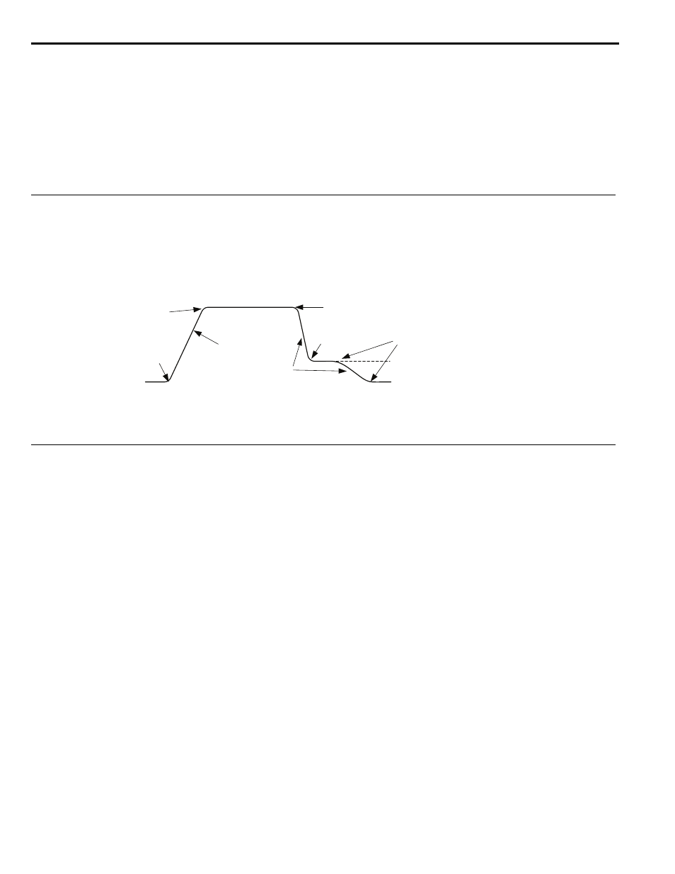
◆ Accel/Decel Ramp and Jerk Settings
Acceleration and deceleration ramps are set using the C1-
parameters. Use the C2-
parameters to adjust the jerk
at the start of acceleration or deceleration.
explains how accel/decel ride and jerk settings can be used to adjust the ride profile.
Figure 4.13
Figure 4.17 Accel/Decel Ramp and the Jerk Function
Units used to set the acceleration and deceleration ramp as well as the Jerk function change with the setting of parameter
o1-03. Refer to
Digital Operator Display Unit Selection on page 105
for details.
◆ Inspection Operation
■
Start Condition in Inspection Operation
NOTICE: Always turn off the RUN command before changing the setting of parameters d1-18 (Speed Reference Selection Mode), b1-
01 (Speed Reference Selection), or H1-
(Multi-Function Digital Inputs). If the RUN command is on when changing any of these
settings, the motor may unexpectedly start running, and could result in injury.
Inspection operation is performed when an Up or Down signal is input while one of the following conditions is true:
• Parameter d1-18 is set to 0 or 3 and the selected speed is higher than d1-28 but lower than d1-29.
• Parameter d1-18 is set to 1 or 2 and a digital input programmed for Inspection Operation Speed (H1- = 54) is
enabled.
Inspection Operation uses the same acceleration characteristics and brake sequence at start as normal operation.
The carrier frequency is set to 2 kHz during Inspection Operation, but can be changed using parameter C6-21.
■
Stop Condition in Inspection Operation
To stop the drive during Inspection Operation, either remove the Up or Down command or reset the input terminal for
Inspection Operation.
A deceleration ramp can be set for Inspection Operation using parameter C1-15.
• If C1-15 = 0.00, the drive immediately applies the brake, shuts off the drive output, and opens the motor contactor, i.e.,
the multi-function output terminals set for “Brake Control” (H2- = 50) and “Output Contactor Control”
(H2- = 51) are cleared.
• If C1-15 > 0.00, the drive decelerates to stop at the rate set to C1-15, then applies the brake, shuts the output off, and
opens the motor contactor.
C1-02
C2-01
C2-03
C2-04
C2-05 (Jerk Below Leveling Speed)
d1-26 (Leveling Speed)
C2-02
(Jerk at
Accel End)
(Jerk at
Accel Start)
C1-01
(Accel Ramp 1)
(Decel Ramp 1)
(Jerk at
Decel Start)
(Jerk at
Decel End)