Powering up the drive and operation status display, Alarm (alm) led displays, Powering up the drive – Yaskawa L1000E AC Drive Technical Manual for CIMR-LE Models for Elevator Applications User Manual
Page 92: Status display, 2 using the led monitor/digital operator, Table 4.2 alarm (alm) led status and contents

4.2 Using the LED Monitor/Digital Operator
92
YASKAWA ELECTRIC SIEP YAIL1E 01A YASKAWA AC Drive L1000E Technical Manual
◆ Powering Up the Drive and Operation Status Display
■
Powering Up the Drive
Perform the following power-off checks before applying main power to the drive.
WARNING! Electrical Shock Hazard. Do not contact live electrical parts. Failure to comply could result in death or serious injury. Never
touch the output terminals directly with your hands or allow the output lines to come into contact with the drive case.
WARNING! Sudden Movement Hazard. Operating a drive with untested emergency circuits could result in death or serious injury.
Always check the operation of drive fast stop circuits and any additional emergency circuits after they are wired. Fast stop circuits are
required to provide safe and quick shutdown of the drive.
WARNING! Sudden Movement Hazard. Ensure start/stop and safety circuits are wired properly and in the correct state before
energizing the drive. Failure to comply could result in death or serious injury from moving equipment.
■
Status Display
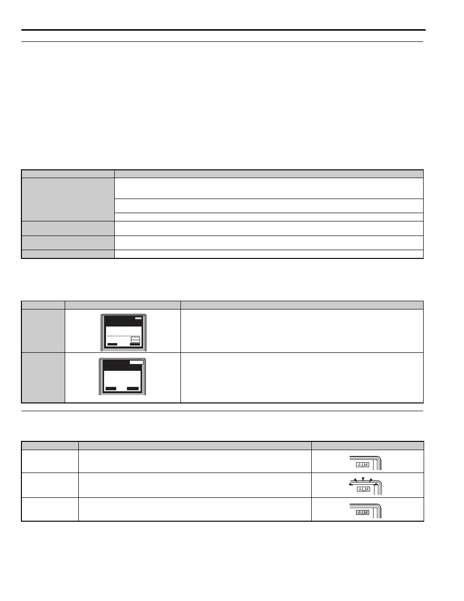
When the power supply to the drive is turned on, the digital operator lights will appear as follows:
◆ ALARM (ALM) LED Displays
Table 4.2 ALARM (ALM) LED Status and Contents
Power-off Checks
Description
Power supply voltage
Ensure the power supply voltage is correct on the supply side of the disconnect, before applying power to the drive.
200 V class: 3-phase 200 to 240 Vac 50/60 Hz
400 V class: 3-phase 380 to 480 Vac 50/60 Hz
Properly wire the power supply input terminals (R/L1, S/L2, T/L3). Check for correct wiring, terminals are tightened, and there are no loose wire
strands.
Check for proper grounding of drive and motor.
Drive output terminals and motor ter-
minals
Properly wire drive output terminals U/T1, V/T2, and W/T3 with motor terminals U/T1, V/T2, and W/T3. Check for correct wiring, terminals
are tightened, and there are no loose wire strands.
Control circuit terminals
Check control circuit terminal connections. Check that control circuit terminals are correctly wired, terminals are tightened, and there are no
loose wire strands.
Drive control terminal status
Open all control circuits to the drive I/O terminal block.
No.
Name
Description
Normal Operation
The data display area in the upper half of the display, displays the speed reference. DRV is displayed.
Fault
External fault (example)
Data displayed varies by the type of fault.
Refer to Fault Displays, Causes, and Possible Solutions on page 276
for more information and possible solutions. ALM LED is lit and DRV displayed.
State
Content
Display
Illuminated
When the drive detects an alarm or error.
Flashing
• When an alarm occurs.
• When oPE is detected.
• When a fault or error occurs during Auto-Tuning.
Off
Normal operation (no fault or alarm).
DIGITAL OPERATOR JVOP-180
ALM
- MODE -
U1-01= 0.00%
U1-02= 0.00%
U1-03= 0.00A
DRV
Speed Ref (OPR)
Rdy
FWD
RSEQ
LREF
YEA_
c o m -
DIGITAL OPERATOR JVOP-180
ALM
- MODE -
EF3
Ext Fault S3
DRV
FWD
RESET
YEA_
c o m -