Digital operation display functions and levels – Yaskawa Matrix Converter User Manual
Page 103
Digital Operation Display Functions and Levels
5-
3
Digital Operation Display Functions and Levels
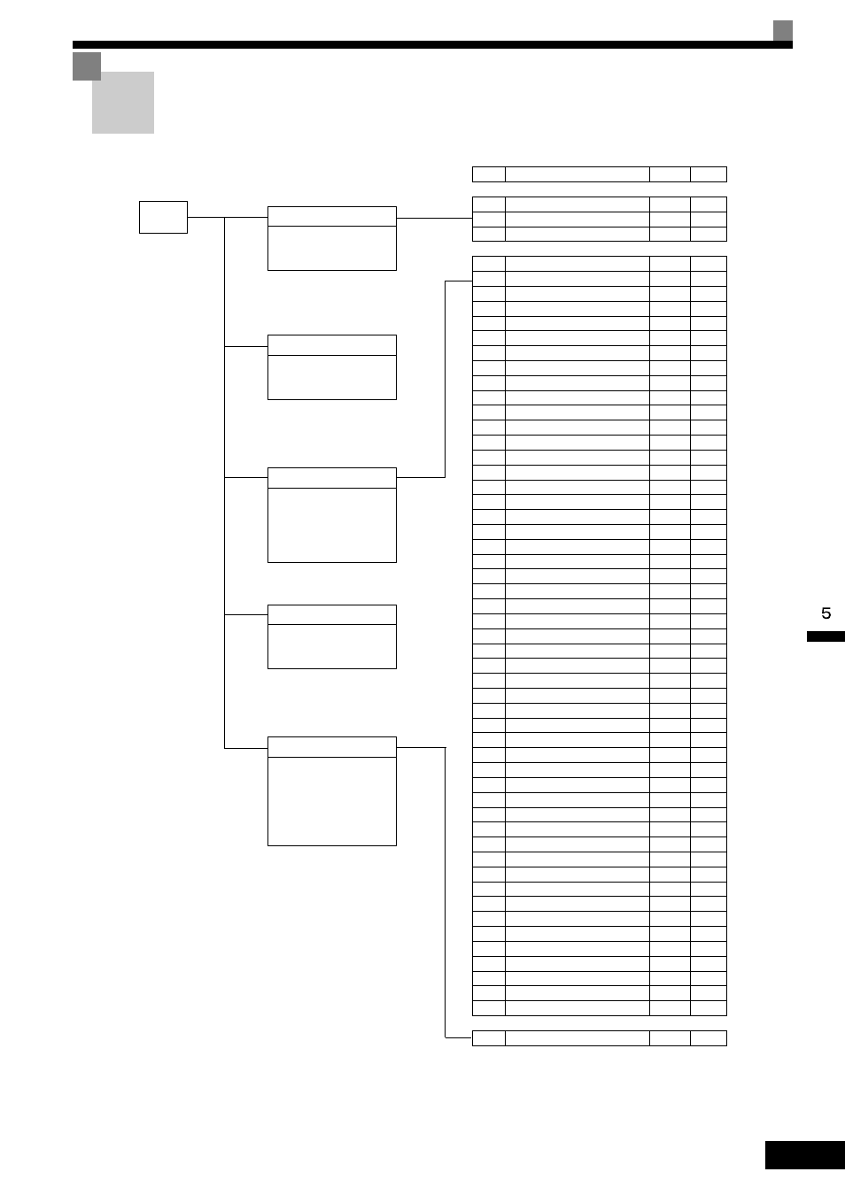
The following illustration shows the menu screens and display hierarchy of the digital operator.
MENU
Drive Mode
MxC can be begin to run the
application, and the operation
status can be viewed.
Quick Programming Mode
Quick setting mode:
Sets or monitors the parame-
ters of QUICK-START (Q).
Advanced Programming Mode
Program Mode:
Sets or monitors the parame-
ters. The items that can be
monitored depend on the set-
ting of the access level.
Verify Mode
Parameters changed from the
default settings can be moni-
tored or set.
Auto-Tuning Mode
Auto-Tuning:
If the line-to-line resistance for
vector control or V/f Control
Method is measured, automat-
ically sets motor parameters
by inputting Auto-Tuning data
(from motor nameplate).
No.
Function
Display
Page
U1
Status Monitor Parameters
Monitor
5-57
U2
Fault Trace
Fault Trace
5-62
U3
Fault History
Fault History
5-63
A1
Initialize Mode
Initialization
5-7
A2
User-Specified Setting Mode
User
Parameter
5-8
b1
Operation Mode Selections
Sequence
5-9
b2
DC Injection Braking
DC Braking
5-10
b3
Speed Search
Speed
Search
5-11
b4
Timer Function
Delay Timers
5-12
b5
PID Control
PID Control
5-12
b6
Dwell Functions
Reference
Hold
5-14
b7
Droop Control
Droop
Control
5-14
b9
Zero-Servo
Zero Servo
5-15
C1
Acceleration/Deceleration
Accel/Decel
5-16
C2
S-Curve Acceleration/Deceleration
S-Curve
Acc/Dcc
5-17
C3
Motor Slip Compensation
Motor-Slip
Comp
5-17
C4
Torque Compensation
Torque
Comp
5-18
C5
Speed Control (ASR)
ASR Tuning
5-19
C6
Carrier Frequency
Carrier Freq
5-19
d1
Preset Reference
Preset
Reference
5-20
d2
Reference Limits
Reference
Limits
5-21
d3
Jump Frequencies
Jump
Frequencies
5-22
d4
Reference Frequency Hold
Sequence
5-22
d5
Torque Control
Torque Control
5-23
d6
Field Weakening
Field-
weakening
5-24
E1
V/f Pattern
V/f Pattern
5-25
E2
Motor Setup
Motor
Setup
5-26
E3
Motor 2 V/f Pattern
V/f Pattern 2
5-27
E4
Motor 2 Setup
Motor Setup
2
5-27
F1
PG Option Setup
PG Option
Setup
5-29
F2
Analog Reference Card
AI-14 Setup
5-30
F3
Digital Reference Card
DI-08, 16
Setup
5-31
F4
Analog Monitor Cards
AO-08, 12
Setup
5-31
F5
Digital Output Cards
DO-02,08
Setup
5-32
F6
Communications Option Cards
ComOPT
Setup
5-33
H1
Multi-Function Digital Inputs
Digital
Inputs
5-34
H2
Multi-Function Digital Outputs
Digital
Outputs
5-37
H3
Analog Inputs
Analog
Inputs
5-39
H4
Multi-Function Analog Outputs
Analog
Outputs
5-41
H5
MEMOBUS Communications
Serial Com
Setup
5-42
L1
Motor Overload
Motor
Overload
5-43
L2
Power Loss Ridethrough
PwrLoss
Ridethru
5-44
L3
Stall Prevention
Stall
Prevention
5-45
L4
Reference Detection
Ref
Detection
5-46
L5
Fault Restart
Fault Restart
5-47
L6
Torque Detection
Torque
Detection
5-47
L7
Torque Limits
Torque Limit
5-48
L8
Hardware Protection
Hdwe
Protection
5-49
n1
Hunting Prevention Function
Hunting Prev
5-50
n2
Speed Feedback Protection Control
AFR
5-51
n5
Feed Forward
Feedfoward
Cont
5-51
o1
Monitor Select
Monitor
Select
5-52
o2
Multi-Function Selections
Key
Selections
5-53
o3
Copy Function
COPY
Function
5-54
T1
Motor Auto-Tuning
Auto-Tuning
5-55