Yaskawa Matrix Converter User Manual
Page 131
Parameter Tables
5-
31
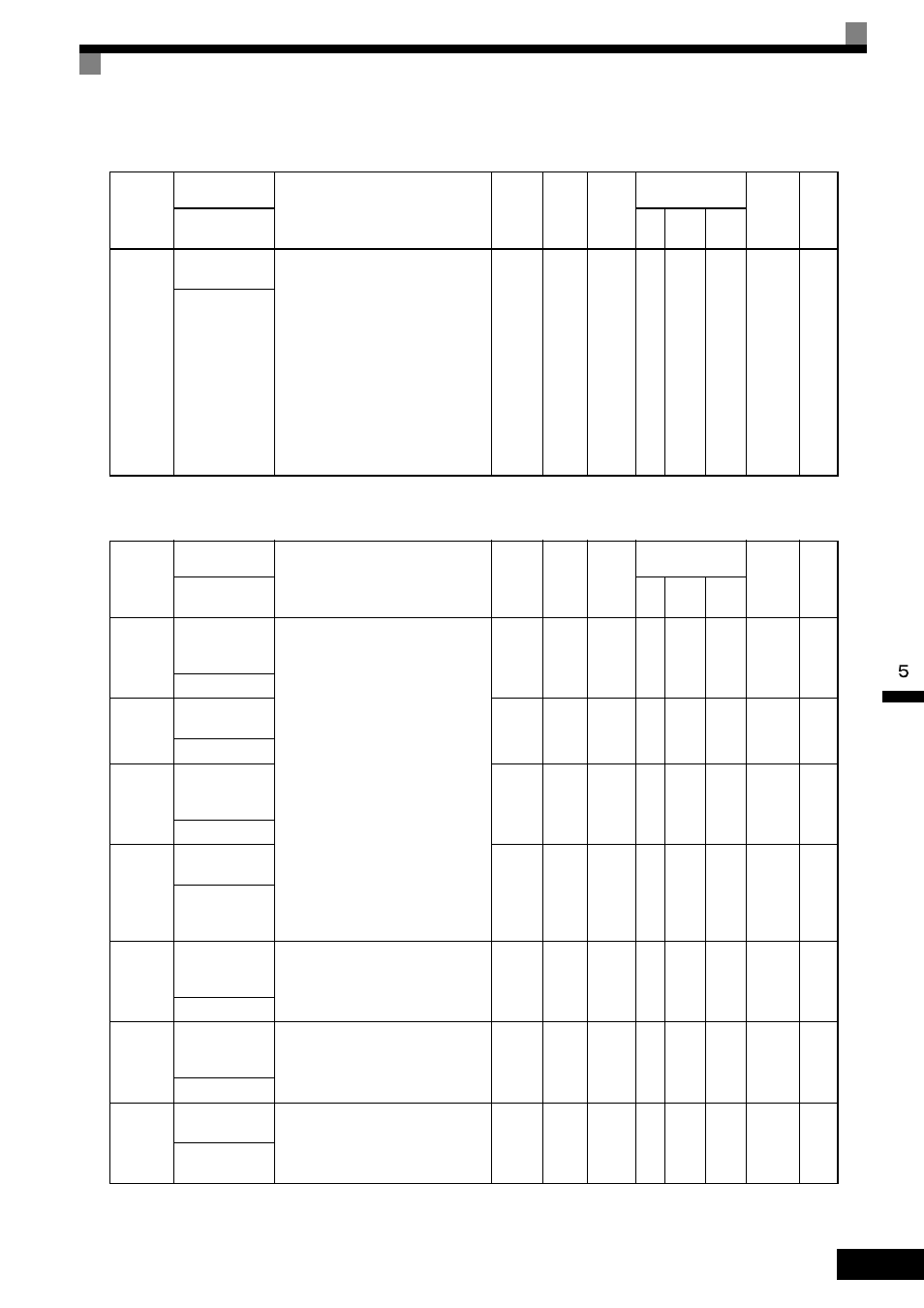
F3: Digital Reference Card
F4: Analog Monitor Cards
* The CH1 output can be adjusted when the F4-02 or F4-05 setting is displayed in Quick, Advanced, or Verify Mode while the motor is stopped.
The CH2 output can be adjusted when the F4-04 or F4-06 setting is displayed in Quick, Advanced, or Verify Mode while the motor is stopped.
For analog output, the value equivalent to 100% of output value of monitored item is multiplied by the gain setting and the set bias is added.
Parameter
Number
Name
Description
Setting
Range
Default
Change
during
Run
Control
Methods
MEMO-
BUS
Register
Page
Display
V/f
Open
Loop
Vector
Flux
Vector
F3-01
DI-08 / DI-16H2
Input Selection
Sets the function of the DI-08 or the DI-
16H2 digital input option card.
0: BCD 1% unit
1: BCD 0.1% unit
2: BCD 0.01% unit
3: BCD 1 Hz unit
4: BCD 0.1 Hz unit
5: BCD 0.01 Hz unit
6: BCD (5-digit) 0.01 Hz unit (enabled
only when DI-16H2 is used).
7: Binary input
When o1-03 is set to 2 or higher, the input
will be BCD, and the units will change to
the o1-03 setting.
0 to 7
0
No
A
A
A
390H
6-142
DI Input
Parameter
Number
Name
Description
Setting
Range
Default
Change
during
Run
Control
Methods
MEMO-
BUS
Register
Page
Display
V/f
Open
Loop
Vector
Flux
Vector
F4-01
AO-08/AO-12
Channel 1 Moni-
tor Selection
Effective when the Analog Monitor Card
is used.
Monitor selection:
Set the number of the monitor item to be
output. (U1-)
Items that can be set differ in accordance
with the selected control modes.
Gain:
Set the multiple of 10 V for outputting
monitor items.
For information on the parameters for
which analog output is possible, refer to
U: Monitors.
When the AO-12 Analog Monitor Card is
used, outputs of
± 10 V are possible. To
output
± 10 V, set F4-07 or F4-08 to 1.
When the AO-08 Analog Monitor Card is
used, only outputs of 0 to +10 V are pos-
sible.
A meter calibration function is available.
*
1 to 99
2
No
A
A
A
391H
6-80
AO Ch1 Select
F4-02
AO-08/AO-12
Channel 1 Gain
0.00 to
2.50
1.00
Yes
A
A
A
392H
6-80
AO Ch1 Gain
F4-03
AO-08/AO-12
Channel 2 Moni-
tor Selection
1 to 99
3
No
A
A
A
393H
6-80
AO Ch2 Select
F4-04
AO-08/AO-12
Channel 2 Gain
0.00 to
2.50
0.50
Yes
A
A
A
394H
6-80
AO Ch2 Gain
F4-05
AO-08/AO-12
Channel 1 Output
Bias
Sets the channel 1 item bias to 100%/10
V when the Analog Monitor Card is used.
-10.0 to
10.0
0.0%
Yes
A
A
A
395H
6-80
AO Ch1 Bias
F4-06
AO-08/AO-12
Channel 2 Output
Bias
Sets the channel 2 item bias to 100%/10
V when the Analog Monitor Card is used.
-10.0 to
10.0
0.0%
Yes
A
A
A
396H
6-80
AO Ch2 Bias
F4-07
AO-12 Channel 1
Signal Level
0: 0 to 10 VDC
1: -10 to +10 VDC
0 or 1
0
No
A
A
A
397H
6-80
AO Opt Level
Ch1