Operation errors – Yaskawa Matrix Converter User Manual
Page 336
Protective and Diagnostic Functions
7-
15
Operation Errors
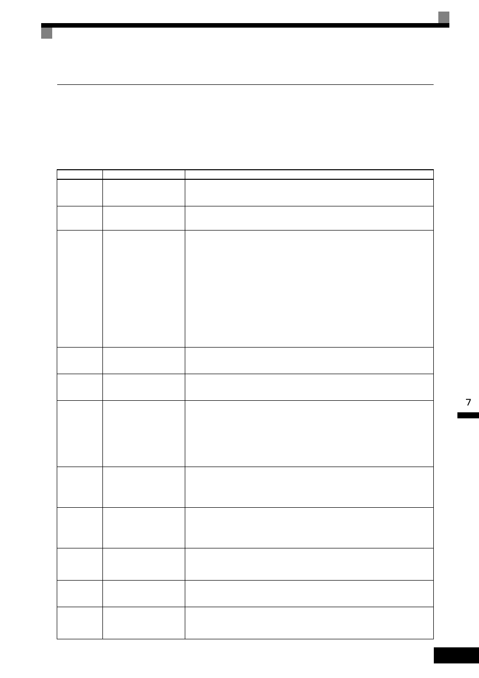
An operation error will occur if there is an invalid setting or a contradiction between two parameter settings.
The MxC cannot be started until the parameters have been set correctly (the alarm output and fault contact
outputs will not operate either).
When an operation error has occurred, refer to the following table to identify and correct the cause of the error.
Table 7.3 Operation Error Displays and Possible Incorrect Settings
Display
Meaning
Possible Incorrect Settings
OPE01
kVA
Selection
Incorrect MxC Capacity
Setting
The MxC capacity setting doesn't match the MxC being used. Contact your Yaskawa
representative.
OPE02
Limit
Parameter Setting
Range Error
The parameter setting is outside of the valid setting range. Press the ENTER key on
the digital operator to display OPE fault parameter (U1-34).
OPE03
Terminal
Multi-Function Input
Selection Error
One of the following errors has been made when setting the Multi-Function Digital
Input Terminal Function Selection (H1-01 to H1-10).
• The same setting has been selected for two or more multi-function inputs.
• An Up or Down Command was selected independently (they must be used
together.)
• The Up/Down Commands (10 and 11) and Accel/Decel Ramp Hold (A) were
selected at the same time.
• Speed Search 1 (61, maximum output frequency) and Speed Search 2 (62. set fre-
quency) were selected at the same time.
• The Up/Down Commands (10 and 11) were selected while PID Function Setting
(b5-01) was enabled.
• Positive and Negative Speed Commands have not been set at the same time.
• The Emergency Stop Command NO and NC have been set at the same time.
OPE05
Sequence
Select
Option Card Selection
Error
The option card was selected as the frequency reference source by setting b1-01 to 3,
but an option card isn't connected (C option).
OPE06
PG Opt
Missing
Control Method Selec-
tion Error
Flux Vector Control was selected by setting A1-02 to 3, but a PG Speed Control
Card isn't connected.
OPE07
Analog
Selection
Multi-Function Analog
Input Selection Error
The same setting has been selected for the analog input selection and the PID func-
tion selection.
• H3-09 = B and H6-01 = 1
• H3-09 = C and H6-01 = 2
b1-01 (Frequency Reference Selection) is set to 4 (pulse input) and H6-01 (Terminal
RP Pulse Train Input Function Selection) is set to a value other than 0 (frequency
reference).
OPE08
Ctrl Func
Error
Parameter Selection
Error
A setting has been made that is not required in the current control method. Example:
A function used only with Open Loop Vector Control was selected for V/f control.
Press the ENTER key on the digital operator to display OPE fault parameter (U1-
34).
OPE09
PID Select
Error
PID Control Selection
Error
The following settings have been made at the same time.
• b5-01 (PID Function Setting) has been set to a value other than 0.
• b5-15 (PID Sleep Function Start Level) has been set to a value other than 0.
• b1-03 (Stopping Method Selection) has been set to 2 or 3.
OPE10
V/f Ptrn
Setting
V/f Data Setting Error
Parameters E1-04, E1-06, E1-07, and E1-09 do not satisfy the following conditions:
• E1-04 (FMAX)
≥ E1-06 (FA) > E1-07 (FB) ≥ E1-09 (FMIN)
• E3-02 (FMAX)
≥ E3-04 (FA) > E3-05 (FB) ≥ E3-07 (FMIN)
OPE20
Factory
Setting Err
Default Error
The defaults were not done.
• Precautions on Control Board Replacement on page 8-3.
ERR
EEPROM
R/W Err
EEPROM Write Error
A verification error occurred when writing EEPROM.
• Try turning the power supply off and then on again.
• Try setting the parameters again.