Drive mode, How to operate the mxc in the drive mode, Operation modes – Yaskawa Matrix Converter User Manual
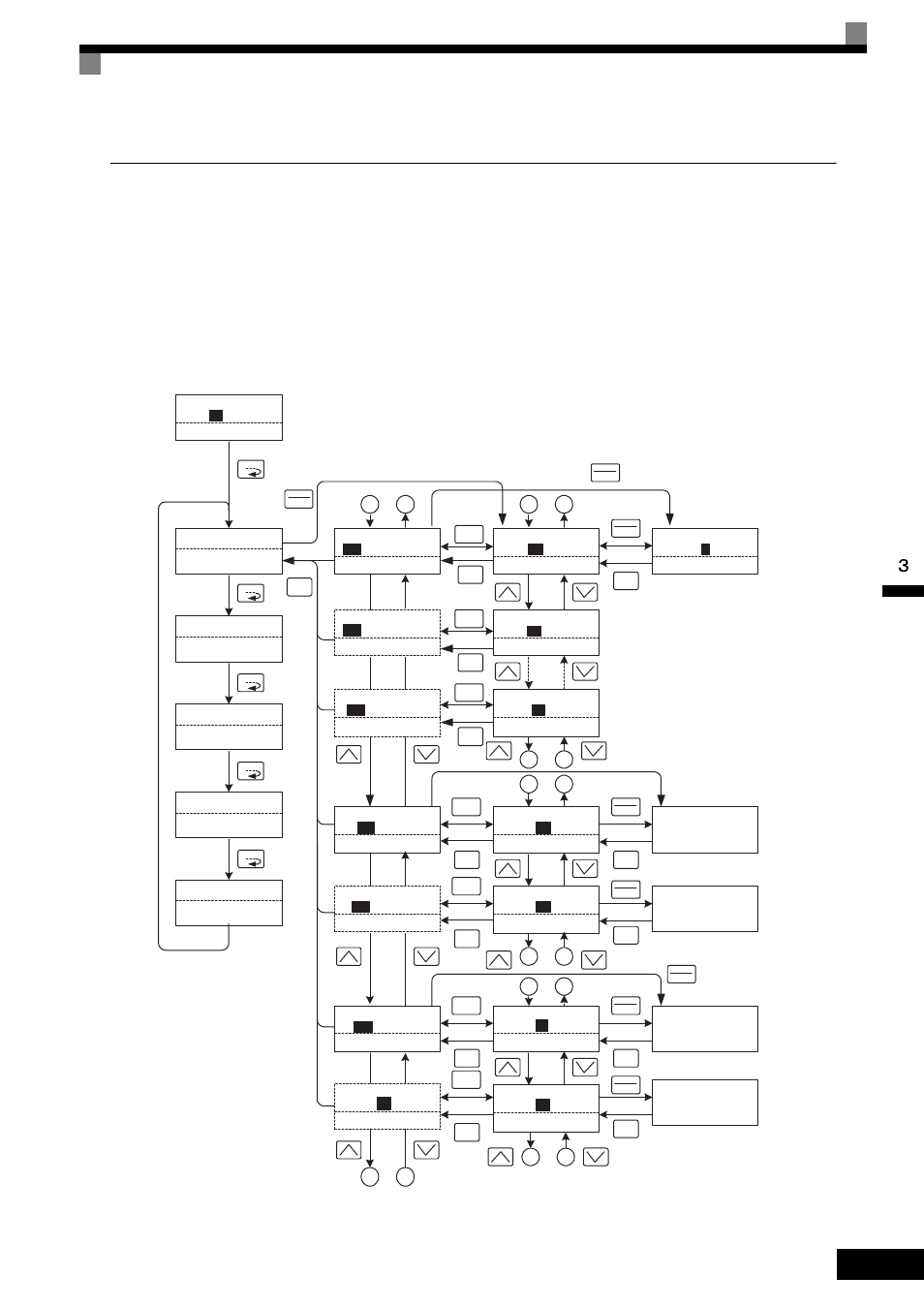
Page 75: Fig 3.4 operations in drive mode
Operation Modes
3-
7
Drive Mode
Once in the Drive Mode, the user can now instruct the MxC to begin operating the motor. The following mon-
itor displays can be viewed while in the Drive Mode: frequency reference, output frequency, output current,
output voltage, as well as fault information and the fault history.
When b1-01 (Frequency Reference Selection) is set to 0, the frequency can be changed from the value that
appears in the frequency setting display. Use the up arrow and right arrow keys to change parameter settings.
Any changes will be saved once the DATA/ENTER key is pushed.
How to Operate the MxC in the Drive Mode
Key operations in the Drive Mode are shown in the following figure.
Fig 3.4 Operations in Drive Mode
Frequency Ref
-DRIVE-
U1-02=60.00Hz
U1-03=10.05A
** Main Menu **
-DRIVE-
Operation
** Main Menu **
-QUICK-
Quick Setting
** Main Menu **
-ADV-
Programming
** Main Menu **
-VERIFY-
Modified Consts
** Main Menu **
-A.TUNE-
Auto-Tuning
U1-
01
=60.00Hz
Monitor
-DRIVE-
U1-02=60.00Hz
U1-03=10.05A
U1
- 01=60.00Hz
MENU
ESC
DATA
ENTER
Frequency Ref
-DRIVE-
U1-02=60.00Hz
U1-03=10.05A
U1-
01
=60.00Hz
Frequency Ref
-DRIVE-
(0.00
←→60.00)
̍0.00Hz̍
U1 - 01=
0
60.00Hz
MENU
MENU
MENU
MENU
㧪
RESET
DATA
ENTER
ESC
DATA
ENTER
Monitor display
Default display
Mode selection
display
Display at startup
Fault Trace
-DRIVE-
U2-02= OV
U2-03=60.00Hz
U2
- 01=OC
Fault History
-DRIVE-
U3-02= OV
U3-03= OH
U3
- 01= OC
Output Freq
-DRIVE-
U1-04= 2
U1-03=10.05A
U1-
02
=60.00Hz
FAN Elapsed Time
-DRIVE-
U1-01=60.00Hz
U1-02=60.00Hz
U1-
40
= 10H
1
2
1
2
Last Fault
-DRIVE-
U3-02=OV
U3-03=OH
U3 -
01
= OC
Fault Message 2
-DRIVE-
U3-03= OH
U3-04= UV
U3 -
02
= OV
㧪
RESET
ESC
5
6
5
6
A
B
A
B
Current Fault
-DRIVE-
U2-02=OV
U2-03=60.00Hz
U2 -
01
= OC
Last Fault
-DRIVE-
U3-03=60.00Hz
U3-04=60.00Hz
U2 -
02
= OV
3
4
3
4
㧪
RESET
ESC
U2 - 01= OC
U2 - 02= OV
Over Current
DC Bus Overvolt
DATA
ENTER
ESC
DATA
ENTER
ESC
U3 - 01= OC
Over Current
DATA
ENTER
ESC
U3 - 02= OV
DC Bus Overvolt
DATA
ENTER
ESC
The fault name will be
displayed if the DATA/ENTER
key is pressed while a parameter
is being displayed for which a
fault code is being displayed.
Rdy
Rdy
Rdy
Rdy
Rdy
Rdy
Rdy
Rdy
Rdy
Rdy
Rdy
Rdy
The default display will not be
displayed when using an
analog reference.
ESC
Monitor
-DRIVE-
U1-04= 2
U1-03=10.05A
U1
- 02=60.00Hz
Rdy
㧪
RESET
ESC
Monitor
-DRIVE-
U1-01=60.00Hz
U1-02=60.00Hz
U1
- 40
= 10H
Rdy
㧪
RESET
ESC
Rdy
Rdy
Rdy
Fault Trace
-DRIVE-
U3-03=60.00Hz
U3-04=60.00Hz
U2
- 02 = OV
Rdy
㧪
RESET
ESC
Fault Message 2
-DRIVE-
U3-03= OH
U3-04= UV
U3 -
02
= OV
Rdy
㧪
RESET
ESC
DATA
ENTER