U3: fault history – Yaskawa Matrix Converter User Manual
Page 163
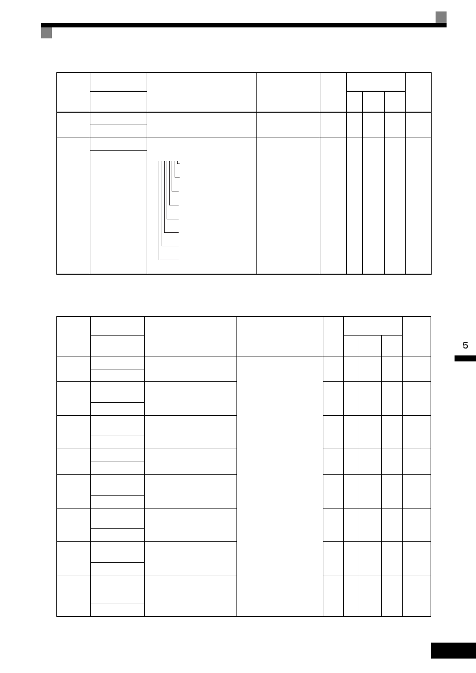
Parameter Tables
5-
63
* Applicable for the Varispeed AC with software versions PRG: 1050 or later.
Note: The error trace does not include the following errors: CPF00, 01, 02, 03, and power faults.
U3: Fault History
* Applicable for the Varispeed AC with software versions PRG: 1050 or later.
Note: The error log does not include the following errors: CPF00, 01, 02, 03, and power faults.
U2-24
*
Power frequency
Monitors the input power supply fre-
quency in the MxC.
10 V: 60 Hz
(0 V to +10V possible)
0.1 Hz
A
A
A
7E9H
Power Frequency
U2-25
*
Input Power Info
Information on the input power supply
No output available
-
A
A
A
7EAH
Power Status
Parameter
Number
Name
Description
Output Signal Level
during Multi-Function
Analog Output
Min.
Unit
Control
Methods
MEMO-
BUS
Register
Display
V/f
Open
Loop
Vector
Flux
Vector
U3-01
Most recent fault
The error contents of 1st previous
fault.
No output available
-
A
A
A
90H
Last Fault
U3-02
Second most
recent fault
The error contents of 2nd previ-
ous fault.
-
A
A
A
91H
Fault Message 2
U3-03
Third most recent
fault
The error contents of 3rd previous
fault.
-
A
A
A
92H
Fault Message 3
U3-04
Fourth/oldest fault The error contents of 4th previous
fault.
-
A
A
A
93H
Fault Message 4
U3-05
Cumulative opera-
tion time at fault
The total operating time when the
1st previous fault occurred.
1 hr
A
A
A
94H
Elapsed Time 1
U3-06
Accumulated time
of second fault
The total operating time when the
2nd previous fault occurred.
1 hr
A
A
A
95H
Elapsed Time 2
U3-07
Accumulated time
of third fault
The total operating time when the
3rd previous fault occurred.
1 hr
A
A
A
96H
Elapsed Time 3
U3-08
Accumulated time
of fourth/oldest
fault
The total operating time when the
4th previous fault occurred.
1 hr
A
A
A
97H
Elapsed Time 4
Parameter
Number
Name
Description
Output Signal
Level during Multi-
Function Analog
Output
Min.
Unit
Control
Methods
MEMO-
BUS
Register
Display
V/f
Open
Loop
Vector
Flux
Vector
bit0: Power detect
0: Not 1: Detect
bit1: Phase Direction
0: For 1: Rev
bit2: Rated Power Frequency
0: 60 Hz 1: 50 Hz
bit3: SRC Detect
0: Not 1: Detect (SRC)
bit4: FDEV Detect
0: Not 1: Detect (FDEV)
bit5: AUV Detect
0: Not 1: Detect (AUV)
bit6: FSTABLED detect
0: Not 1: End (FSTABLE)
bit7: RFINI_FLAG detect
0: Not 1: End (RFINI_FLAG)
U2-25=
00000000