Yaskawa Matrix Converter User Manual
Page 335
7
-14
* 1. Available for Varispeed AC with software versions PRG: 1050 or higher.
* 2. For details on replacement, refer to Chapter 8 Maintenance and Inspection.
EF7
(flashing)
Ext Fault
S7
External Fault (Input Terminal S7)
An external fault was input from a
multi-function input terminal (S3 to
S12).
• Reset external fault inputs to the
multi-function inputs.
• Remove the cause of the external
fault.
EF8
(flashing)
Ext Fault
S8
External Fault (Input Terminal S8)
EF9
(flashing)
Ext Fault
S9
External Fault (Input Terminal S9)
EF10
(flashing)
Ext Fault
S10
External Fault (Input Terminal S10)
EF11
(flashing)
Ext Fault
S11
External Fault (Input Terminal S11)
EF12
(flashing)
Ext Fault
S12
External Fault (Input Terminal S12)
FBL
(flashing)
Feed-
back
Loss
PID Feedback Reference Lost
A PID feedback reference loss was
detected (b5-12 = 2) and the PID feed-
back input was less than b5-13 (PID
feedback loss detection level) for
longer than the time set in b5-14 (PID
feedback loss detection time).
-
-
CE
(flashing)
MEMO-
BUS
Com Err
MEMOBUS Communications Error
Normal reception was not possible for
2 s or longer after received control
data.
-
Check the communications devices
and signals.
BUS
(flashing)
Option
Com Err
Option Card Communications
Error
A communications error occurred in a
mode where the Run Command or a
frequency reference is set from an
Communications Option Card.
-
Check the communications devices
and signals.
CALL
(flashing)
Com
Call
Communications on Standby
Control data was not normally
received when power was turned on.
-
Check the communications devices
and signals.
LT-C
*1
(flashing)
Mainte-
nance
Electrolytic Capacitor Maintenance
Timer
Monitor U1-61 has reached 100%.
The electrolytic capacitors have
reached their estimated maintenance
time period.
Reset constant o2-18 to “0%” after
replacing
*2
the PCB board.
LT-F
*1
(flashing)
Fan
Mainte-
nance
Cooling Fan Maintenance Timer
Monitor U1-63 has reached 100%.
The cooling fan has reached its esti-
mated maintenance time period.
Replace the cooling fan
*2
and set con-
stant o2-10 to “0H”.
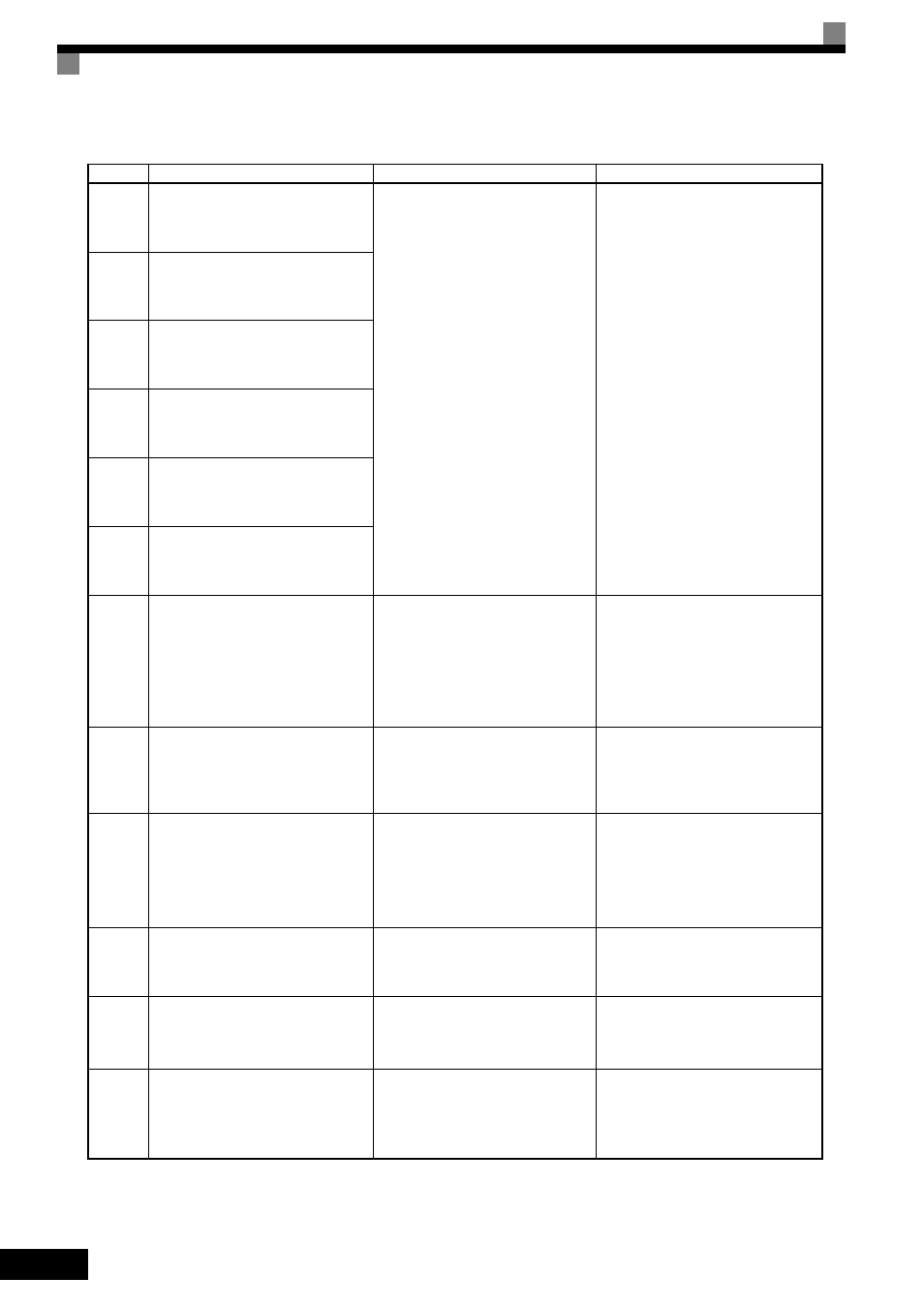
Table 7.2 Alarm Displays and Processing (Continued)
Display
Meaning
Probable causes
Corrective Actions