Communications connection terminal, Procedure for communicating with the plc – Yaskawa Matrix Converter User Manual
Page 248
Individual Functions
6-
83
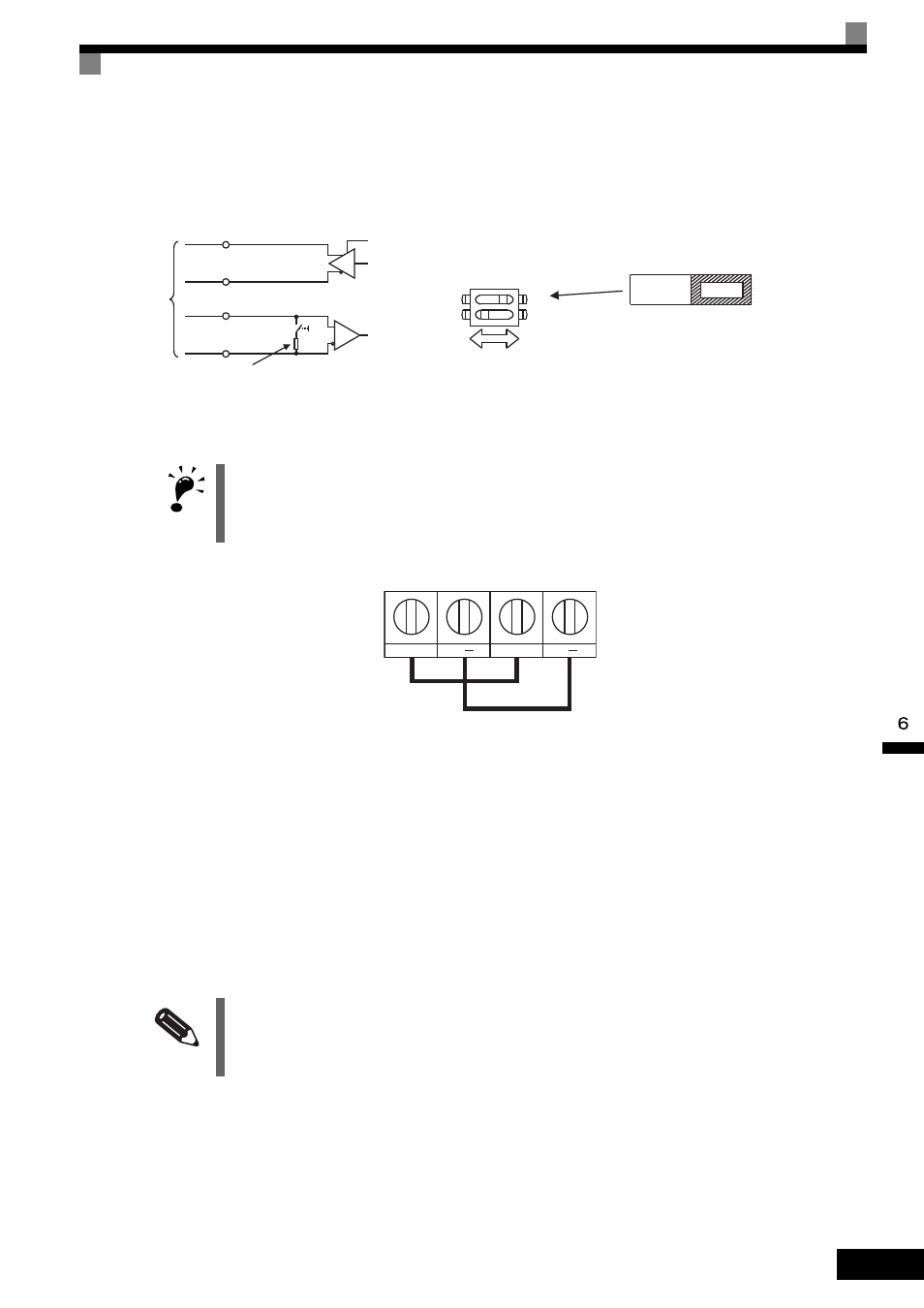
Communications Connection Terminal
MEMOBUS communications use the following terminals: S+, S-, R+, and R-. Set the terminating resistance
by turning on pin 1 of switch S1 for the last MxC only, as seen from the PLC.
Fig 6.58 Communications Connection Terminal
Procedure for Communicating with the PLC
Use the following procedure to perform communications with the PLC.
1. Turn off the power supply and connect the communication cable between the PLC and the MxC.
2. Turn on the power supply.
3. Set the required communications parameters (H5-01 to H5-07) using the digital operator.
4. Turn off the power supply, and check that the digital operator display has completely disappeared.
5. Turn on the power supply once again.
6. Perform communications with the PLC.
IMPORTANT
1. Separate the communication cables from the main circuit cables and other wiring and power cables.
2. Use shielded cables for the communication cables, connect the shield cover to the MxC earth terminal, and
arrange the terminals so that the other end is not connected to prevent operating errors due to noise.
3. When using RS-485 communications, connect S+ to R+, and S- to R-, on the MxC exterior.
INFO
Set the timer on the master to monitor response time from the slave. Set the master so that if the slave does
not respond to the master within the set time, the same command message will be sent from the master
again.
RS-422A
or RS-485
R+
R-
SW1
Terminating resistance
(1/2 W, 110
Ω)
S+
S-
+
-
S1
O
F
F
1
2
Terminating
resistance
OFF
ON
R+
R
S+
S