Yaskawa Matrix Converter User Manual
Page 72
3
-4
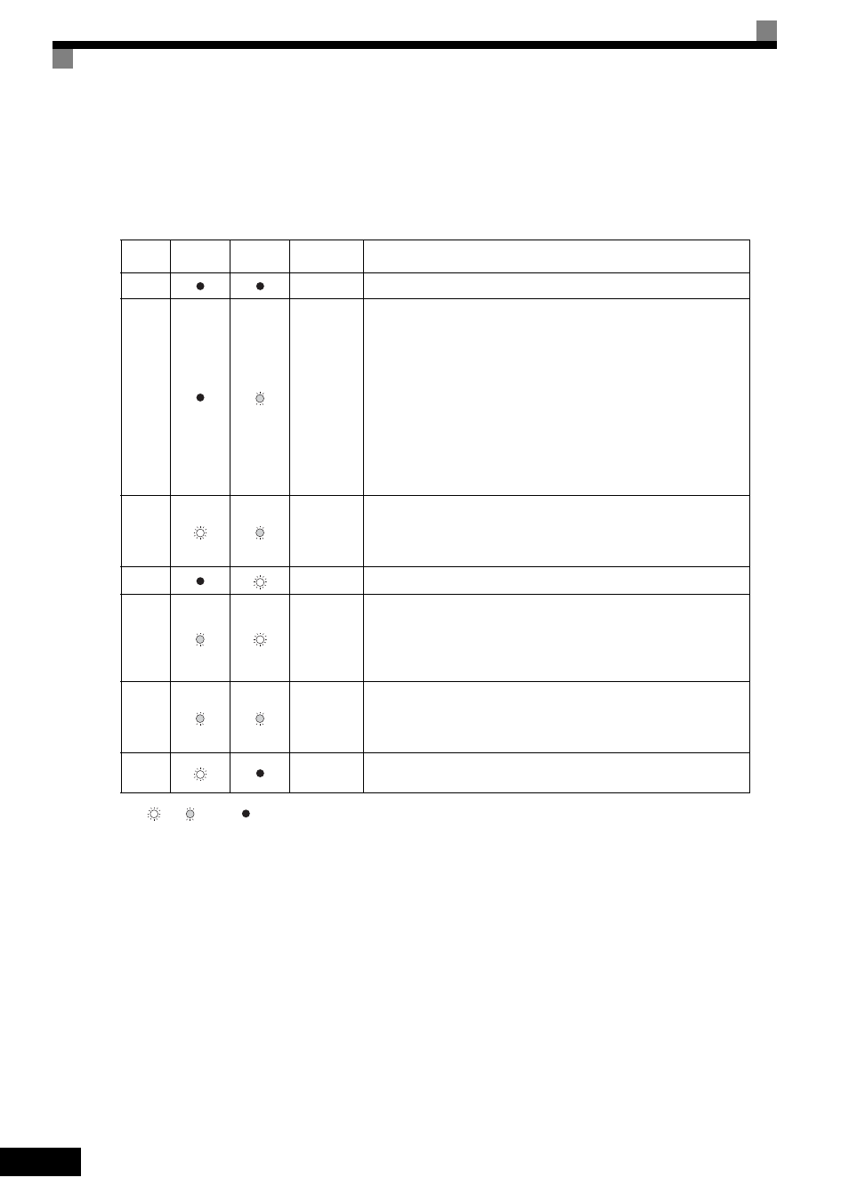
The following table shows the relationship between the indicators on the RUN and STOP keys as well as the
MxC operation status.
The LED indicators can be on, off, or flash to indicate the operating status.
Note:
: Lit
: Flashing : Not lit
* If planning to run the MxC again, first turn off the Run Command and Emergency Stop Command from the control circuit terminal, and then re-send the
Run Command.
Table 3.2 Relation of MxC to RUN and STOP LED Indicators
Priority
RUN
Indicator
STOP
Indicator
MxC
Status
Conditions
1
Stopped
Power supply has been shut off.
2
Stopped*
Emergency stop
• A Stop Command is sent from the digital operator when using the con-
trol circuit terminals to operate the MxC.
• An Emergency Stop Command was sent from the control circuit termi-
nal.
The MxC has been switched from LOCAL to REMOTE when the Run
Command is still sent from one of the external terminals (LOCAL = oper-
ation using the digital operator, REMOTE: operation using the control
circuit terminals).
Switched from the Quick or Advanced Quick Programming Mode to the
Drive Mode while the Run Command is being sent via an external termi-
nal.
3
Stopped
The MxC is trying to run at a frequency below the minimum output fre-
quency.
The Run Command is carried out when the External Baseblock Com-
mand using the multi-function contact input terminal is issued.
4
Stopped
Stopped
5
Running
The MxC is decelerating to a stop.
During DC injection braking when using the multi-function contact input
terminal.
During initial excitation of DC injection braking while the MxC is
stopped.
6
Running
During emergency deceleration
• Stop Command is sent from the digital operator when operating the
MxC using the control circuit terminals.
• Emergency Stop Command is sent from the control circuit terminal.
7
Running
Run Command is issued.
During initial excitation of DC injection braking when starting the MxC.