Yaskawa Matrix Converter User Manual
Page 261
6
-96
Monitor Functions
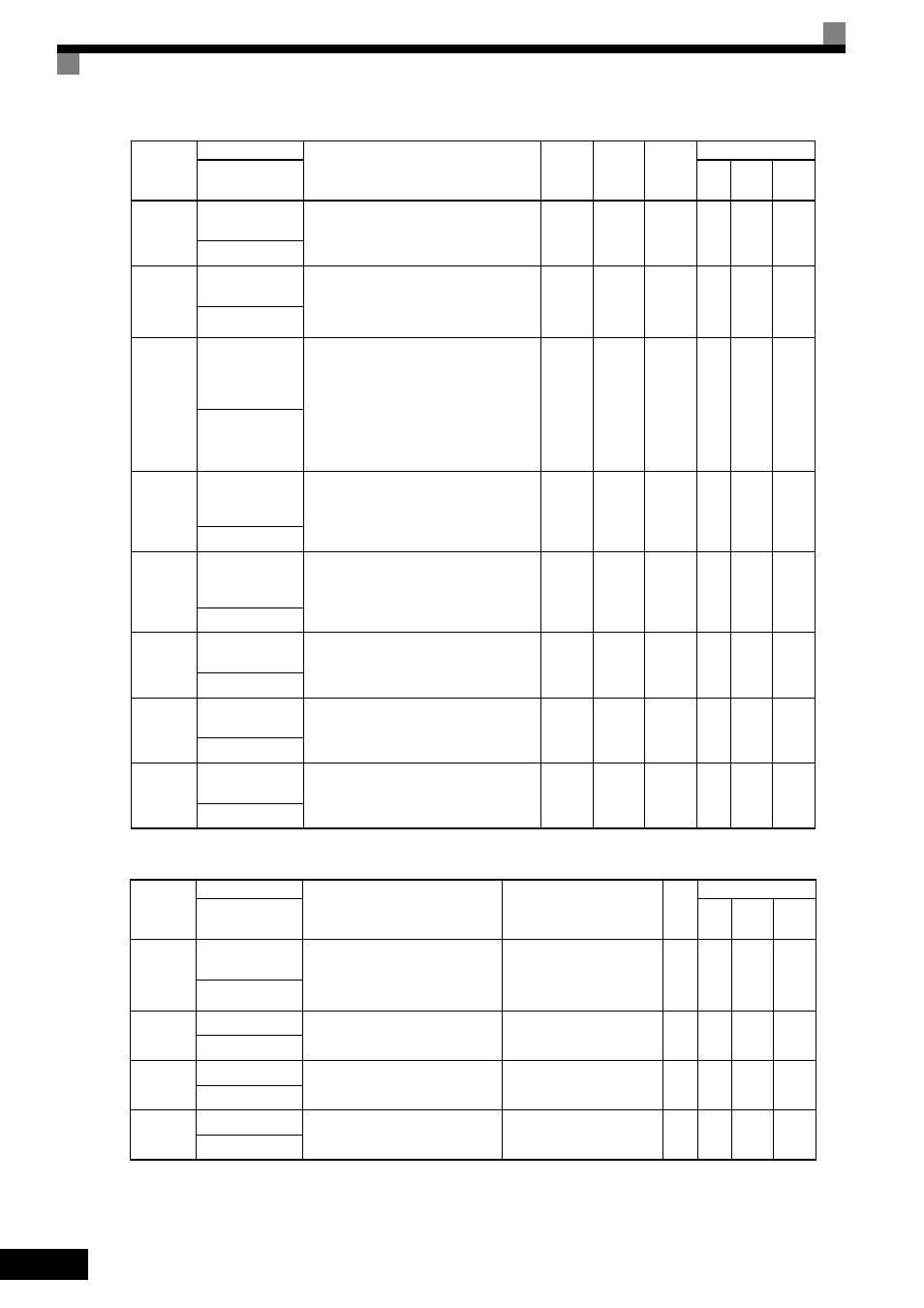
b5-10
PID Output Gain
Setting
Sets output gain.
0.0 to
25.0
1.0
No
A
A
A
Output Gain
b5-11
PID Output
Reverse Selection
0: 0 limit when PID output is negative.
1: Reverses when PID output is negative.
0 limit when reverse prohibit is selected using
b1-04.
0 or 1
0
No
A
A
A
Output Rev Sel
b5-12
PID Feedback Ref-
erence Missing
Detection Selec-
tion
0: No detection of loss of PID feedback.
1: Detection of loss of PID feedback.
Operation continues during detection,
with the malfunctioning contact not oper-
ating.
2: Detection of loss of PID feedback.
Coasts to stop during detection, and fault
contact operates.
0 to 2
0
No
A
A
A
Fb los Det Sel
b5-13
PID Feedback
Loss Detection
Level
Sets the PID feedback loss detection level as a
percent units, with the maximum output fre-
quency at 100%.
0 to 100
0%
No
A
A
A
Fb los Det Lvl
b5-14
PID Feedback
Loss Detection
Time
Sets the PID feedback loss detection level in s
units.
0.0 to
25.5
1.0 s
No
A
A
A
Fb los Det Time
b5-15
PID Sleep Func-
tion Start Level
Set the PID sleep function start level as a fre-
quency.
0.0 to
120.0
0.0 Hz
No
A
A
A
PID Sleep Level
b5-16
PID Sleep Delay
Time
Set the delay time until the PID sleep function
starts in seconds.
0.0 to
25.5
0.0 s
No
A
A
A
PID Sleep Time
b5-17
PID Accel/Decel
Time
Set the accel/decel time for PID reference in
seconds.
0.0 to
25.5
0.0 s
No
A
A
A
PID Acc/Dec Time
Parameter
Number
Name
Description
Output Signal Level
During Multi-Function
Analog Output
Min.
Unit
Control Methods
Display
V/f
Open
Loop
Vector
Flux
Vector
U1-24
PID feedback
value
Monitors the feedback value when
PID control is used.
The input for the max frequency cor-
responds to 100%.
10 V: Max frequency
(-10 V to +10 V possible)
0.01
%
A
A
A
PID Feedback
U1-36
PID input volume
PID feedback volume
Given as maximum frequency/100%
10 V: Max frequency
(-10 V to +10 V possible)
0.01
%
A
A
A
PID Input
U1-37
PID output volume PID control output
Given as maximum frequency/100%
10 V: Max frequency
(-10 V to +10 V possible)
0.01
%
A
A
A
PID Output
U1-38
PID target value
PID target value
Given as maximum frequency/100%
10 V: Max frequency
0.01
%
A
A
A
PID Setpoint
Parameter
Number
Name
Description
Setting
Range
Default
Change
during
Run
Control Methods
Display
V/f
Open
Loop
Vector
Flux
Vector