Wiring main circuit terminals, Applicable wire gauges and closed-loop connectors – Yaskawa Matrix Converter User Manual
Page 41
Wiring Main Circuit Terminals
2-
7
Wiring Main Circuit Terminals
Applicable Wire Gauges and Closed-Loop Connectors
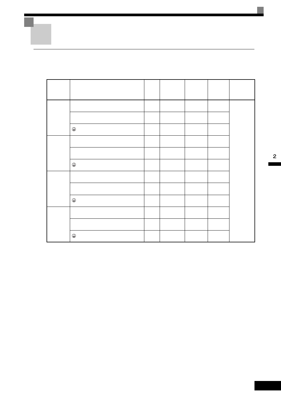
Select the appropriate wires and crimp terminals listed in Table 2.1 through Table 2.3.
* 1. Connect the momentary power loss compensation unit. Do not connect the power to these terminals.
* 2. Normally not used. Do not connect the power to these terminals.
Note: The wire gauge recommendations for the following conditions: continuous operation at rated current, vinyl-sheathed wire (max: 75
°C), and ambient
temperature within 30
°C.
Table 2.1 200 V Class Wire Gauges
MxC Model
CIMR-
Terminal Symbol
Terminal
Screws
Tightening
Torque
(N•m)
Possible
Wire
Gauges
mm
2
(AWG)
Recom-
mended
Wire Gauge
mm
2
(AWG)
Wire Type
ACA25P5
R/L1, S/L2, T/L3, U/T1, V/T2, W/T3
M5
2 to 2.4 Nm
8 to 14
(8 to 6)
8
(8)
Power cables,
e.g., 600 V
vinyl power
cables
r2*
2
, s2*
2
, t2*
2
, p1*
1
, n1*
1
M4
1.3 to 1.4
Nm
2 to 3.5
(14 to 12)
2
(14)
M8
9 to 10 Nm
8 to 22
(8 to 4)
8
(8)
ACA2011
R/L1, S/L2, T/L3, U/T1, V/T2, W/T3
M5
2 to 2.4 Nm
14
(6)
14
(6)
r2*
2
, s2*
2
, t2*
2
, p1*
1
, n1*
1
M4
1.3 to 1.4
Nm
2 to 3.5
(14 to 12)
2
(14)
M8
9 to 10 Nm
14 to 22
(6 to 4)
14
(6)
ACA2022
R/L1, S/L2, T/L3, U/T1, V/T2, W/T3
M8
9 to 10 Nm
38 to 60
(1 to 1/0)
38
(1)
r2*
2
, s2*
2
, t2*
2
, p1*
1
, n1*
1
M4
1.3 to 1.4
Nm
2 to 3.5
(14 to 12)
2
(14)
M8
9 to 10 Nm
22 to 38
(4 to 2)
22
(4)
ACA2045
R/L1, S/L2, T/L3, U/T1, V/T2, W/T3
M10
18 to 23 Nm
100
(4/0)
100
(4/0)
r2
*2
, s2
*2
, t2
*2
, p1
*1
, n1
*1
M4
1.3 to 1.4
Nm
2 to 3.5
(14 to 12)
2
(14)
M8
9 to 10 Nm
5 to 60
(1 to 1/0)
50
(1)