Wiring examples, Using a vs operator – Yaskawa Matrix Converter User Manual
Page 382
10
-12
Wiring Examples
This section provides wiring examples to connect peripheral devices to the main circuits, examples of wir-
ing a transformer to MxC I/O, and other aspects of MxC wiring.
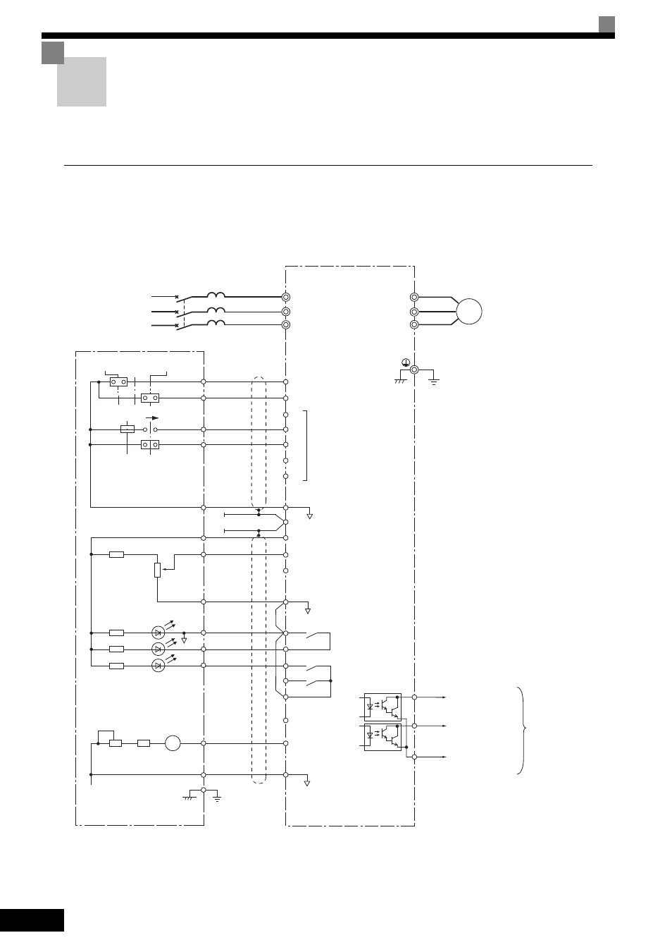
Using a VS Operator
This example shows wiring for using a VS Operator. The VS Operator model number is JVOP-95• or JVOP-
96 •.
CIMR-ACA25P5 (200 V class 5.5 kW)
Fig 10.4
3-phase power
MCCB
T
S
R
MxC
Motor
IM
Ground to 100
Ω max
Forward Run Command
(forward run when closed)
Reverse Run Command
(reverse run when closed)
Multi-function contact inputs
Sequence common (0 V)
Shield wire connection
terminal
Master speed (0 to 10 V, 20 k
Ω)
Speed setting power (15 V, 20 mA)
Master speed (4 to 20 mA, 250
Ω)
Fault contact output
P1
P2
PC
Multi-function contact
output (Default: Running
signal)
Frequency meter
MTR CAL
Multi-function
analog output
Multi-function
analog output
(Default: Output
frequency)
Open collector 1
(Default:
Zero-speed signal)
Open collector 2
(Default:
Speed agreement
signal)
Multi-function
output
common
Multi-function
open-collector
output 48 V,
50 mA max
R/L1
S/L2
T/L3
U/T1
V/T2
W/T3
JVOP-95
• , C-96• VS Operator
FWD RUN
RESET
MASTER
AUX
REV RUN
STOP
1
S1
S2
S3
S4
S5
S6
S7
SC
0 V
E
+V
A1
A2
AC
M1
M2
MA
MB
MC
AM
FM
AC
2
4
5
11
15
13
17
9
10
18
F1
F3
E
FREQ SET
SOURCE
RUN
FAULT
FM