Selecting analog monitor items, Adjusting the analog monitor items – Yaskawa Matrix Converter User Manual
Page 245
6
-80
* If the setting display of F4-02 or F4-05 appears when the motor is not rotating in the Quick, Advanced, or Verify Mode, the CH1 output can be adjusted. If
the setting display of F4-04 or F4-06 appear when the motor is not rotating in the Quick, Advanced, or Verify Mode, the CH2 output can be adjusted.
For analog output, multiple gain 100% of the output the items that can be monitored.
Selecting Analog Monitor Items
The digital operator monitor items (U1- [status monitor]) are output from multi-function analog output
terminals FM-AC and AM-AC. Refer to Chapter 5 Parameters and Settings, and set the values for the
part of U1- (status monitor).
Alternatively, monitor items (U1- [status monitor]) will be outputted from analog output option terminal
channels 1 and 2 on analog monitor cards AO-08 and AO-12. Refer to the table of parameters, and set the val-
ues.
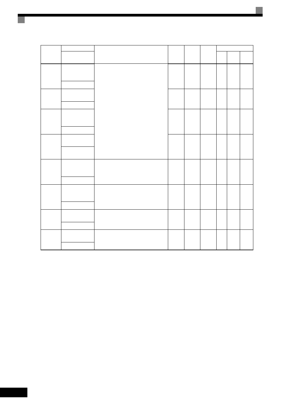
Adjusting the Analog Monitor Items
Adjust the output voltage for multi-function analog output terminals FM-AC and AM-AC using the gain and
bias in H4-02, H4-03, H4-05, and H4-06. Also, adjust the output voltage for output channels 1 and 2 of Ana-
log Output option cards AO-08 and AO-12 using the gain and bias in F4-02, F4-04, F4-05, and F4-06.
Parameter
Number
Name
Description
Setting
Range
Default
Change
during
Run
Control Methods
Display
V/f
Open
Loop
Vector
Flux
Vector
F4-01
AO-08/AO-12
Channel 1 Moni-
tor Selection
Effective when the Analog Monitor Card is
used.
Monitor selection:
Set the number of the monitor item to be out-
put. (U1-)
Items that can be set differ in accordance with
the selected control modes.
Gain:
Set the multiple of 10 V for outputting moni-
tor items.
For information on the parameters for which
analog output is possible, refer to U: Moni-
tors.
When the AO-12 Analog Monitor Card is
used, outputs of
± 10 V are possible. To out-
put
± 10 V, set F4-07 or F4-08 to 1. When the
AO-08 Analog Monitor Card is used, only
outputs of 0 to +10 V are possible.
A meter calibration function is available.
*
1 to 99
2
No
A
A
A
AO Ch1 Select
F4-02
AO-08/AO-12
Channel 1 Gain
0.00 to
2.50
1.00
Yes
A
A
A
AO Ch1 Gain
F4-03
AO-08/AO-12
Channel 2 Moni-
tor Selection
1 to 99
3
No
A
A
A
AO Ch2 Select
F4-04
AO-08/AO-12
Channel 2 Gain
0.00 to
2.50
0.50
Yes
A
A
A
AO Ch2 Gain
F4-05
AO-08/AO-12
Channel 1 Output
Bias
Sets the channel 1 item bias to 100%/10 V
when the Analog Monitor Card is used.
-10.0 to
10.0
0.0
Yes
A
A
A
AO Ch1 Bias
F4-06
AO-08/AO-12
Channel 2 Output
Bias
Sets the channel 2 item bias to 100%/10 V
when the Analog Monitor Card is used.
-10.0 to
10.0
0.0
Yes
A
A
A
AO Ch2 Bias
F4-07
AO-12 Channel 1
Signal Level
0: 0 to 10 VDC
1: -10 to +10 VDC
0 or 1
0
No
A
A
A
AO Opt Level Sel
F4-08
AO-12 Channel 2
Signal Level
0: 0 to 10 VDC
1: -10 to +10 VDC
0 or 1
0
No
A
A
A
AO Opt Level Sel