Installing and wiring option cards, Option card models and specifications – Yaskawa Matrix Converter User Manual
Page 60
2
-26
Installing and Wiring Option Cards
Option Card Models and Specifications
Up to three option cards can be mounted in the MxC. An option card can be mounted into each of the three
slots available on the control board (A, C, and D) shown in Fig 2.24.
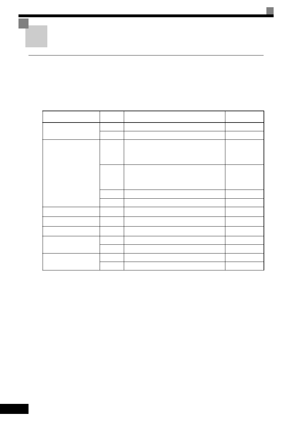
Table 2.11 lists the type of option cards available and their specifications.
* 1. Applicable for the Varispeed AC with software versions PRG: 1051 or later.
* 2. Under development.
* 3. SI-C card with software versions PRG: 0103 or later is applicable for Varispeed AC.
Table 2.11 Option Card Specifications
Card
Model
Specifications
Mounting
Location
PG Speed Control Cards
PG-B2
Phase A/B complimentary inputs
A
PG-X2
Phase A/B line-driver inputs
A
Speed Reference Cards
AI-14U
Input signal levels
0 to 10 V DC (20 k
Ω), 1 channel
4 to 20 mA (250
Ω), 1 channel
Input resolution: 14-bit
C
AI-14B
Input signal levels
0 to 10 V DC (20 k
Ω)
4 to 20 mA (250
Ω), 3 channels
Input resolution: 13-bit and signed bit
C
DI-08
8-bit digital speed reference setting
C
DI-16H2
16-bit digital speed reference setting
C
DeviceNet Interface Card
SI-N1
*1
Supports DeviceNet communications.
C
CANopen Interface Card
SI-S1
*2
Supports CANopen communications.
C
CC-Link Interface Card
SI-C
*3
Supports CC-Link communications.
C
Analog Monitor Card
AO-08
8-bit analog outputs, 2 channels
D
AO-12
12-bit analog outputs, 2 channels
D
Digital Output Card
DO-08
Six photocoupler outputs and 2 relay outputs
D
DO-02C
2 relay outputs
D