Yaskawa Matrix Converter User Manual
Page 284
Individual Functions
6-
119
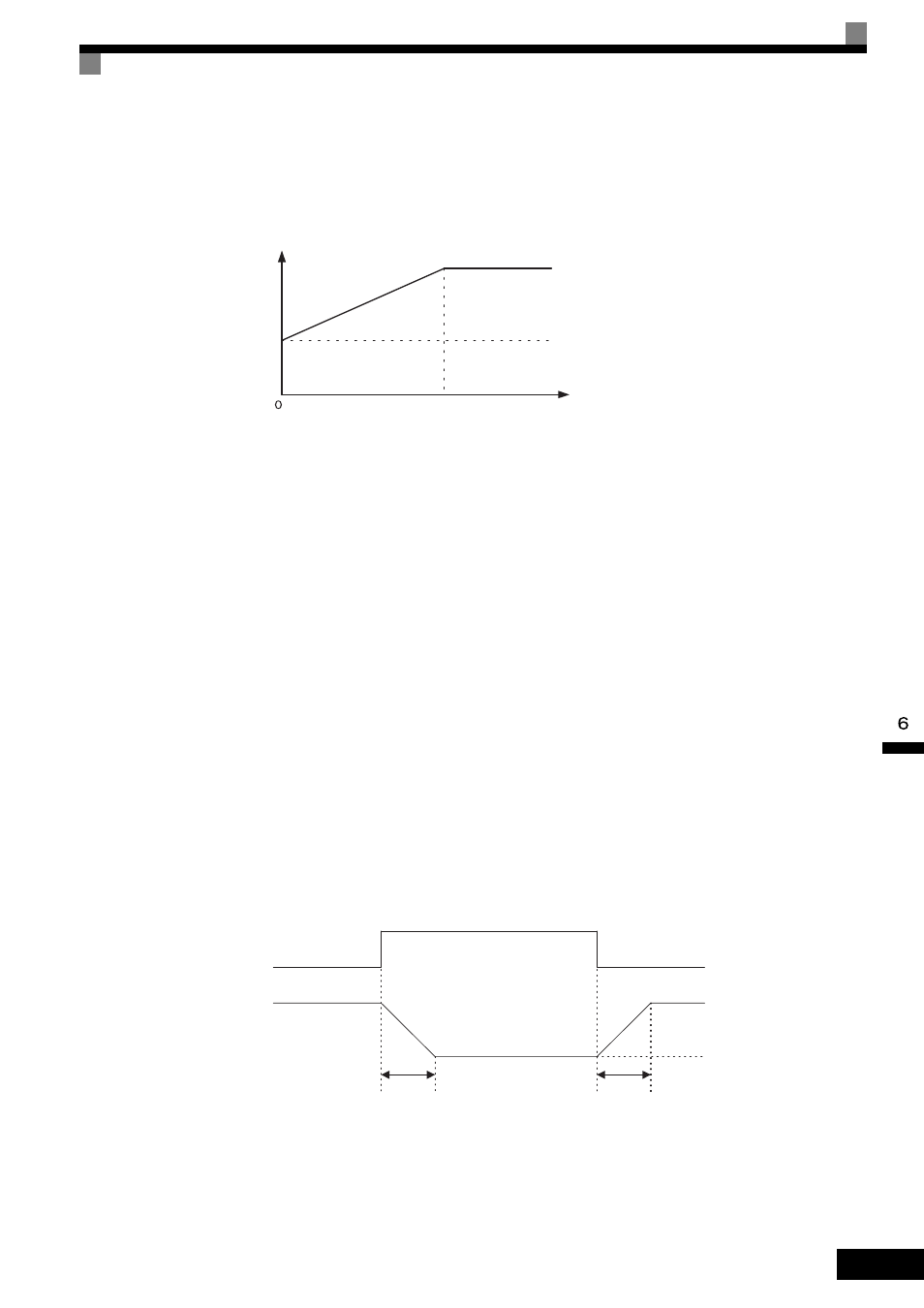
Different Gain Settings for Low-speed and High-speed
Switch between low-speed and high-speed gain when oscillation occurs because of resonance with the
mechanical system at low speed or high speed. The proportional gain P and integral time I can be switched
according to the motor speed, as shown below.
Fig 6.73 Low-Speed and High-Speed Gain Settings
Setting the Gain Switching Frequency (C5-07)
Set the switching frequency to about 80% of the motor operating frequency or the frequency at which oscilla-
tion occurs.
Low-Speed Gain Adjustments (C5-03, C5-04)
Connect the actual load and adjust these parameters at zero-speed. Increase C5-03 (ASR Proportional Gain 2)
until there is no oscillation. Decrease C5-04 (ASR Integral Time 2) until there is no oscillation.
High-Speed Gain Adjustments (C5-01, C5-02)
Adjust these parameters at normal operating speed. Increase C5-01 (ASR Proportional Gain 1) until there is no
oscillation. Decrease C5-02 (ASR Integral Time 1) until there is no oscillation. Refer to Fine-Tuning on page
6-117 for details on making fine adjustments of high-speed operation.
ASR Proportional Gain Switch Setting
When one of the multi-function inputs (H1-01 to H1-10) is set to 77, the input can be used to switch between
C5-01 (ASR Proportional Gain 1) and C5-03 (ASR Proportional Gain 2). Proportional gain 2 is used when the
multi-function input is on. This input has higher priority than the ASR switching frequency set in C5-07.
Fig 6.74 ASR Proportional Gain Switch
P, I
Motor speed (Hz)
P = C5-01
I = C5-02
P = C5-03
I = C5-04
(Low speed)
C5-07
If C5-07 is set to 0, P = C5-01 and I = C5-02.
ASR Gain Switch signal
(a multi-function input)
C5-02
C5-02
off
on
C5-03 gain setting
Proportional gain (P)
Proportional gain
determined
by motor speed.
The gain is changed linearly in integral time 1 (C5-02).