Wiring terminal blocks – Yaskawa Matrix Converter User Manual
Page 66
2
-32
Wiring Terminal Blocks
Use no more than 100 meters of wiring for PG (encoder) signal lines, and keep them separate from power
lines.
Use shielded, twisted-pair cable for pulse inputs and pulse output monitor wires, and connect the shield to the
shield connection terminal.
Wire Gauges (Same for All Models)
Terminal wire gauges are shown in Table 2.14.
Straight Solderless Terminals for Control Circuit Terminals
Yaskawa recommends using straight solderless terminal on signal lines to simplify wiring and improve reli-
ability.
Refer to Straight Solderless Terminal Sizes for specifications.
Closed-Loop Connector Sizes and Tightening Torque
The closed-loop connectors and tightening torques for various wire gauges are shown in Table 2.15.
Wiring Method and Precautions
The wiring method is the same as the one used for straight solderless terminals. Refer to page 2-18. Observe
the following precautions when wiring:
•
Separate the control signal lines for the PG Speed Control Card from main circuit lines and power lines.
•
Connect the shield when connecting to a PG. The shield must be connected to prevent operational errors
caused by noise. Also, do not use any lines that are more than 100 m long. Refer to Fig 2.23 for details on
connecting the shield.
•
Connect the shield to the shield terminal (E), but only if the MxC is not affected by noise from peripheral
devices.
•
Do not solder the wire ends. Doing so may cause a contact fault.
•
When not using straight solderless terminals, strip the wires to a length of approximately 5.5 mm.
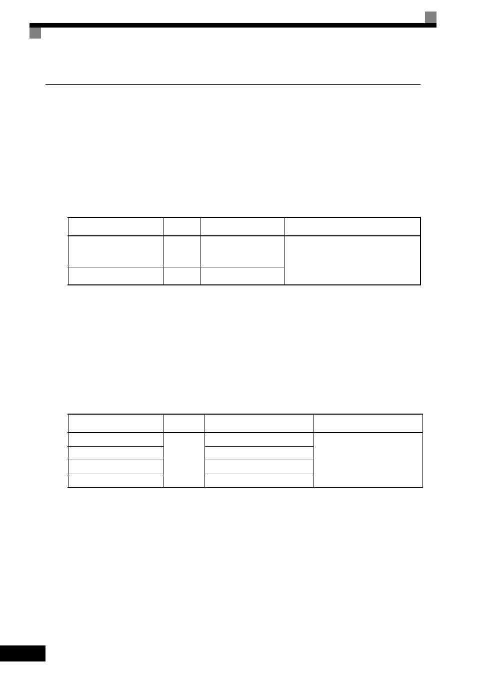
Table 2.14 Wire Gauges
Terminal
Terminal
Screws
Wire Thickness (mm
2
)
Wire Type
Pulse generator power supply
Pulse input terminal
Pulse monitor output terminal
-
Stranded wire: 0.5 to 1.25
Single wire: 0.5 to 1.25
• Shielded, twisted-pair wire
• Shielded, polyethylene-covered, vinyl
sheath cable
(KPEV-S by Hitachi Electric Wire or
equivalent)
Shield connection terminal
M3.5
0.5 to 2
Table 2.15 Closed Loop Connectors and Tightening Torques
Wire Thickness [mm
2
]
Terminal
Screws
Crimp Terminal Size
Tightening Torque (N
• m)
0.5
M3.5
1.25 - 3.5
0.8
0.75
1.25 - 3.5
1.25
1.25 - 3.5
2
2 - 3.5