Parameters and output signals – Yaskawa Matrix Converter User Manual
Page 210
Machine Protection
6-
45
Parameters and Output Signals
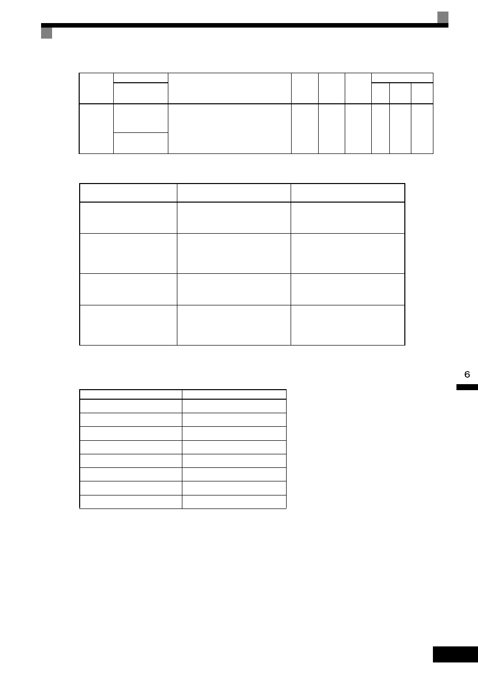
Set the corresponding setting in the multi-function output (H2-01 to H2-05) to output the desired Fref/Fout
Agree signal, Fref/Set Agree signal, or Frequency Detection signal.
L4-04
Speed Agreement
Detection Width
(+/-)
Effective when “Frequency (speed) agree 2,”
“Frequency (FOUT) detection 3,” or “Fre-
quency detection 4” is set for a multi-function
output.
Frequency detection width is set in Hz units.
0.0 to
20.0
2.0 Hz
No
A
A
A
Spd Agree Wdth
+-
Parameter
Number
Name
Function
L4-01
Speed Agree Detection Level
Fref/Set Agree 1
Frequency Detection 1
Frequency Detection 2
L4-02
Speed Agree Detection Width
Fref/Fout Agree 1
Fref/Set Agree 1
Frequency Detection 1
Frequency Detection 2
L4-03
Speed Agree Detection Level (+/-)
Fref/Set Agree 2
Frequency Detection 3
Frequency Detection 4
L4-04
Speed Agree Detection Width (+/-)
Fref/Fout Agree 2
Fref/Set Agree 2
Frequency Detection 3
Frequency Detection 4
Function
Setting
Fref/Fout Agree 1
2
Fref/Set Agree 1
3
Frequency Detection 1
4
Frequency Detection 2
5
Fref/Fout Agree 2
13
Fref/Set Agree 2
14
Frequency Detection 3
15
Frequency Detection 4
16
Parameter
Number
Name
Description
Setting
Range
Default
Change
during
Run
Control Methods
Display
V/f
Open
Loop
Vector
Flux
Vector