Yaskawa Matrix Converter User Manual
Page 392
10
-22
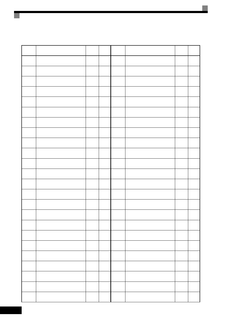
Table 10.2 Parameters (Continued)
H5-06 MxC Transmit Wait Time
5
H5-07 RTS Control Selection
1
H5-10
Unit Selection for Memobus Reg-
ister 0025H
0
L1-01
Motor Overload Protection Selec-
tion
1
L1-02
Motor Overload Protection Time
1.0
L1-03
Motor Overheat Alarm Operation
Selection
3
L1-04
Motor Overheat Fault Operation
Selection
1
L1-05
Motor Temperature Input Filter
Time
0.20
L2-01
Momentary Power Loss Detection
Selection
0
L2-02
Momentary Power Loss
Ridethrough Time
0.5
*2
L2-03
Momentary Power Loss Minimum
Baseblock Time
0.7
*2
L2-04
Momentary Power Loss Voltage
Recovery Ramp Time
1.5
L2-05
Undervoltage Detection Level
190
*3
L2-13
Power Frequency Fault Detection
Gain
1.0
L2-21
Undervoltage-detection Level
150
*3
L2-27
*7
Detection Width of Input Power
Frequency Error
6.0
L3-01
Stall Prevention Selection during
Accel
1
L3-02
Stall Prevention Level during
Acceleration
150
L3-03
Stall Prevention Limit during
Acceleration
50
L3-04
Stall Prevention Selection during
Deceleration
1
L3-05
Stall Prevention Selection during
Run
1
L3-06
Stall Prevention Level during Run
160
L3-14
Stall Prevention Level during
Decel
150
L4-01
Speed Agreement detection Level
0.0
No.
Name
Default
Set-
ting
L4-02 Speed Agreement Detection Width
2.0
L4-03
Speed Agreement Detection
Level(+/-)
0.0
L4-04
Speed Agreement Detection Width
(+/-)
2.0
L4-05
Frequency Reference Loss Detec-
tion Selection
0
L5-01 Number of Auto Restart Attempts
0
L5-02
Auto Restart Operation Selection
0
L6-01 Torque Detection Selection 1
0
L6-02 Torque Detection Level 1
150
L6-03 Torque Detection Time 1
0.1
L6-04 Torque Detection Selection 2
0
L6-05 Torque Detection Level 2
150
L6-06 Torque Detection Time 2
0.1
L7-01 Forward Torque Limit
200
L7-02 Reverse Torque Limit
200
L7-03
Forward Regenerative Torque
Limit
200
L7-04
Reverse Regenerative Torque
Limit
200
L7-06
Torque Limit Integral Time Con-
stant
200
L7-07
Torque Limit Control Method
Selection during Accel/Decel
0
L8-02 Overheat Alarm Level
90
*2
L8-03
Overheat Pre-Alarm Operation
Selection
3
L8-07 Output Phase Loss Protection
0
L8-09
Output Ground Fault Detection
Selection
1
L8-10
Heatsink Cooling Fan Operation
Selection
0
L8-11
Heatsink Cooling Fan Operation
Delay Time
60
No.
Name
Default
Set-
ting