U: monitors, U1: status monitors – Yaskawa Matrix Converter User Manual
Page 157
Parameter Tables
5-
57
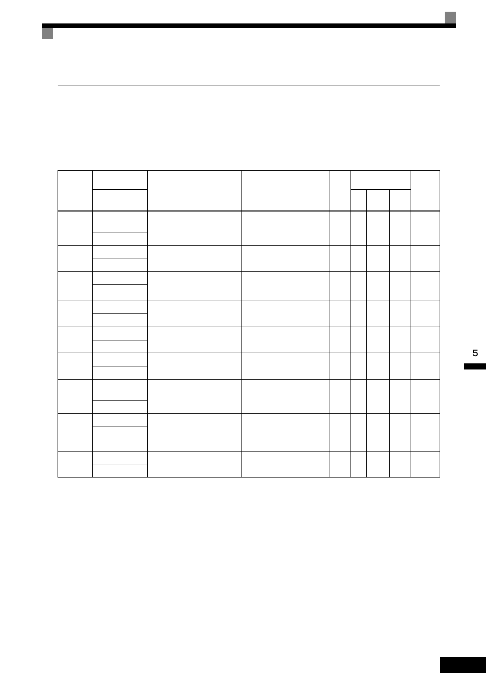
U: Monitors
The following settings are made with the monitor parameters (U parameters): Setting parameters for monitor-
ing in Drive Mode.
U1: Status Monitors
Parameter
Number
Name
Description
Output Signal Level
during Multi-Function
Analog Output
Min.
Unit
Control
Methods
MEMO-
BUS
Register
Display
V/f
Open
Loop
Vector
Flux
Vector
U1-01
Frequency
reference
Monitors/sets the frequency refer-
ence value.
*
10 V: Max frequency
(
−10 V to + 10 V possible)
0.01
Hz
A
A
A
40H
Frequency Ref
U1-02
Output frequency
Monitors the output frequency.
*
10 V: Max frequency
(
−10 V to + 10 V possible)
0.01
Hz
A
A
A
41H
Output Freq
U1-03
Output current
Monitors the output current.
10 V: MxC rated output current
(0 V to +10 V, absolute value
output)
0.1 A
A
A
A
42H
Output Current
U1-04
Control method
Checks the current control
method.
No output available
-
A
A
A
43H
Control Method
U1-05
Motor speed
Monitors the detected motor
speed.
*
10 V: Max frequency
(
−10 V to + 10 V possible)
0.01
Hz
No
A
A
44H
Motor Speed
U1-06
Output voltage
Monitors the output voltage refer-
ence value in the MxC.
10 V: 200 VAC (400 VAC)
(0 V to +10 V output)
0.1
VAC
A
A
A
45H
Output Voltage
U1-07
Control circuit
voltage
Monitors the control circuit volt-
age in the MxC.
10 V: 400 VDC (800 VDC)
(0 V to +10 V output)
1
VDC
A
A
A
46H
PS Voltage
U1-08
Output power
Monitors the output power (inter-
nally detected value).
10 V: MxC capacity
(max applicable motor capac-
ity)
(
−10 V to + 10 V possible)
0.1
kW
A
A
A
47H
Output kWatts
U1-09
Torque reference
Monitors internal torque reference
value for vector control.
10 V: Motor rated torque
(
−10 V to + 10 V possible)
0.1%
No
A
A
48H
Torque Reference
* The unit is set in o1-03 (frequency units of reference setting and monitor).