Yaskawa Matrix Converter User Manual
Page 367
9
-4
* 1. The maximum applicable motor capacity is given for a standard, four-pole Yaskawa motor. When selecting the actual motor and MxC, be sure that the MxC’s
rated current is greater than the motor’s rated current.
* 2. The rated current will vary in accordance with the values of the voltage or impedance of the power supply (including the power transformer, the input reactor, and
wires).
* 3. Required to reduce the rated output current in accordance with the values of the carrier frequencies or control mode.
* 4. Rotational Auto-Tuning is required for the open loop vector or Flux Vector Control.
* 5. The speed control accuracy varies in accordance with the installation condition and motor type. For more details, contact your Yaskawa representative.
* 6. Derating is required for applications that use repetitive loads. To decrease the carrier frequency or to gradually decrease the current, use an MxC with a greater
capacity. For more details, contact your Yaskawa representative.
* 7. If the CIMR-ACA45P5, 4011, 25P5, 2011, or 2022 needs two seconds or more for the momentary power loss ridethrough time, a separate momentary-power-loss
compensation unit is required. Even if the Momentary Power Loss Detection function (L2-01) is enabled, the MxC will run for 2 ms and then stop if a momentary
power loss occurs. Take note of this delay when the MxC is used in various applications.
* 8. The ground fault here is one which occurs in the motor wiring while the motor is running. A ground fault may not be detected in the following cases.
y A ground fault with low resistance which occurs in motor cables or terminals.
y A ground fault occurs when the power is turned on.
* 9. The open chassis is the only type of protective structure available for the MxC models CIMR-ACA4110 and 4160.
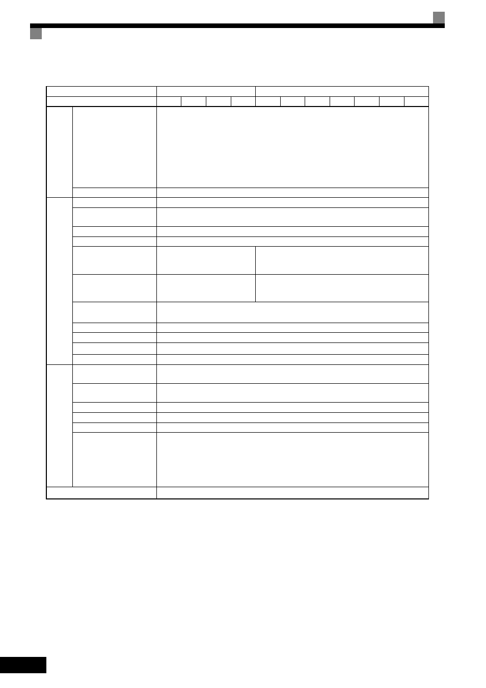
Main control functions
Restarting for momentary power loss, speed search, overtorque detection, torque limits, 17-
speed control (maximum), accel/decel time changes, S-curve accel/decel, 3-wire sequence,
Auto-Tuning (rotational or stationary), dwell functions, cooling fan on/OFF control, slip
compensation, torque compensation, jump frequencies, upper and lower limits for fre-
quency references, DC braking for starting and stopping, PID control with sleep function,
MEMOBUS communications (RS-485/422, 19.2 kbps maximum), fault reset, function
copying, droop control, torque control, speed/torque control switching, etc.
Regenerative function
Provided
Motor protection
Protection by electronic thermal overload relay.
Instantaneous
overcurrent protection
Stops at approx. 200% of rated output current.
Blown fuse protection
Stops if fuse blows.
Overload protection
150% of rated output current per one minute (for carrier frequency of 4 kHz)
Overvoltage protection
Input voltage: Stops if input
power supply voltage is greater
than approx. 250 VAC.
Input voltage: Stops if input power supply voltage is
greater than approx. 550 VAC.
Undervoltage protection
Input voltage: Stops if control
power supply voltage is less
than approx. 150 VAC.
Input voltage: Stops if control power supply voltage is
less than approx. 300 VAC.
Momentary power loss
ridethrough
Stops for 2 ms or more during power loss (default).
Parameter settings allow the unit to continue running if power is restored within 2s.
*7
Cooling fin overheating
Protection by thermistor.
Stall prevention
Stall prevention during acceleration or deceleration while running.
Grounding protection
*8
Protection by electronic circuits. (Overcurrent level)
Charge indicator
Lit until the control-power voltage is approx. 50 V or more.
Ambient operating
temperature
Enclosed, wall-mounted type: -10
°C to + 40°C
Open chassis type: -10
°C to + 45°C
Ambient operating
humidity
95% RH max (with no condensation)
Storage temperature
- 20
°C to + 60°C (short-term temperature during transportation)
Application site
Indoor (no corrosive gas, dust, etc.)
Altitude
1000 m max
Oscillation
200 V Class Inverters of 5.5 to 22 kW and 400 V Class Inverters of 5.5 to 22 kW
10 to 20 Hz: 9.8 m/s2
20 to 55 Hz: 5.9 m/s2
200 V Class Inverters of 45 kW and 400 V Class Inverters of 45 to 160 kW
10 to 20 Hz: 9.8 m/s2
20 to 55 Hz: 2.0 m/s2
Protective structure
Open chassis type (IP00) and enclosed wall-mounted type [NEMA1 (Type 1)]
*9
Table 9.3 Common Specifications (Continued)
Voltage Class (V)
200
400
Model: CIMR-ACAA
25P5
2011
2022
2045 45P5
4011
4022
4045
4075
4110
4160
Control chara
cteri
stics
Protective function
s
Enviro
nment