Standard connection diagrams – Yaskawa Matrix Converter User Manual
Page 45
Advertising
Wiring Main Circuit Terminals
2-
11
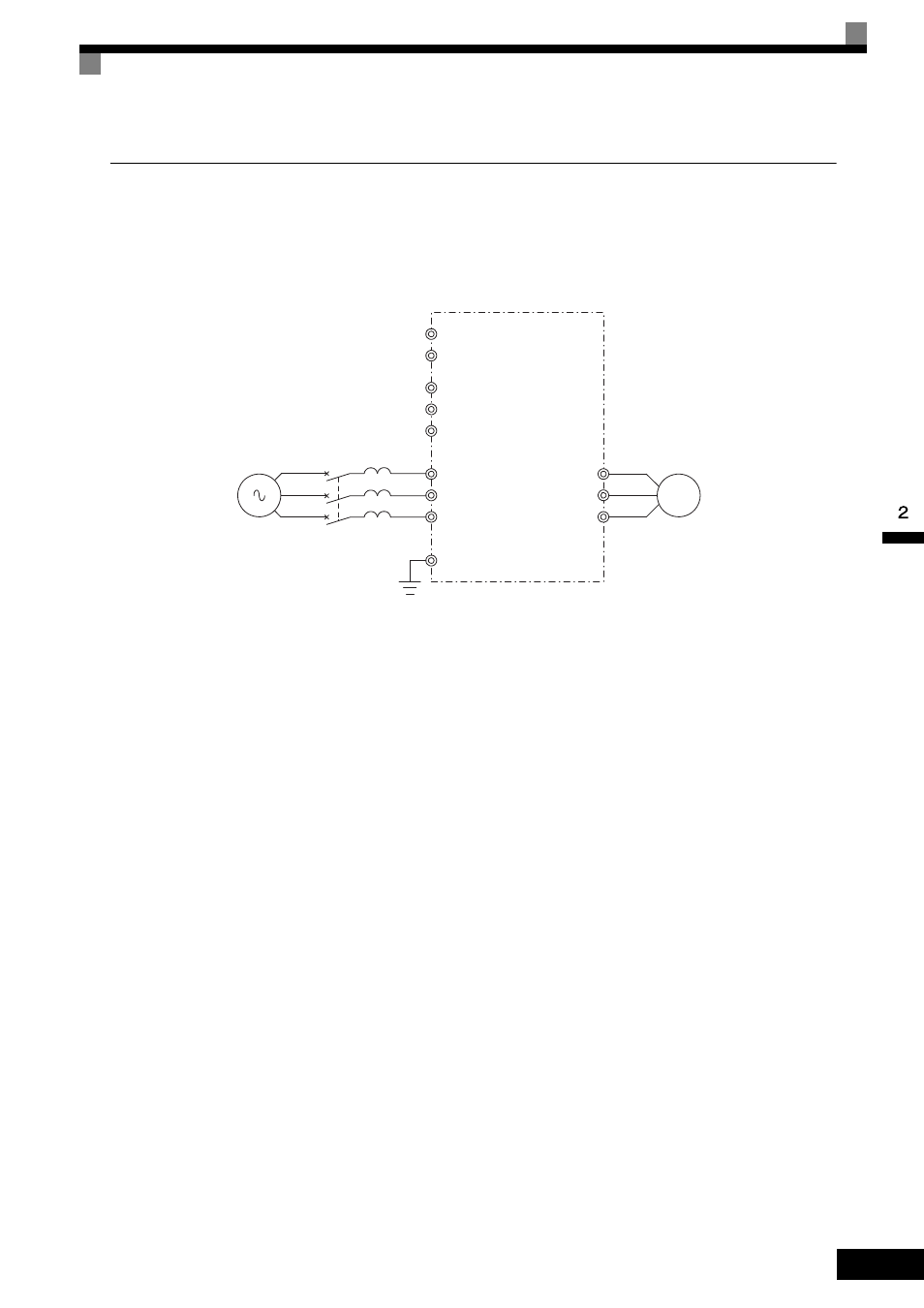
Standard Connection Diagrams
Standard MxC connection diagrams are shown in Fig 2.8. These are the same for both 200 V class and 400 V
class MxCs. The connections depend on the MxC capacity.
CIMR-ACA25P5 to 2045, 45P5 to 4160
* 1. Connect the Momentary Power Loss Compensation unit. Do not connect power to these terminals.
* 2. Normally not used. Do not connect power to these terminals.
* 3. The MxC models CIMR-ACA4110 and 4160 do not have terminals r2, s2, t2, p1 and n1.
Note: Control power is supplied internally from the main circuit power supply for all MxC models.
Fig 2.8 Main Circuit Terminal Connections
3-phase 200 VAC
(400 VAC)
U/T1
V/T2
W/T3
t2
*
2 *3
R/L1
S/L2
T/L3
r2
*
2 *3
s2
*
2 *3
IM
p1
*
1 *3
n1
*
1 *3
Advertising
See also other documents in the category Yaskawa Equipment:
- Tag Generator (30 pages)
- MP3300iec (82 pages)
- 1000 Hz High Frequency (18 pages)
- 1000 Series (7 pages)
- PS-A10LB (39 pages)
- iQpump Micro User Manual (300 pages)
- 1000 Series Drive Option - Digital Input (30 pages)
- 1000 Series Drive Option - CANopen (39 pages)
- 1000 Series Drive Option - Analog Monitor (27 pages)
- 1000 Series Drive Option - CANopen Technical Manual (37 pages)
- 1000 Series Drive Option - CC-Link (38 pages)
- 1000 Series Drive Option - CC-Link Technical Manual (36 pages)
- 1000 Series Drive Option - DeviceNet (37 pages)
- 1000 Series Drive Option - DeviceNet Technical Manual (81 pages)
- 1000 Series Drive Option - MECHATROLINK-II (32 pages)
- 1000 Series Drive Option - Digital Output (31 pages)
- 1000 Series Drive Option - MECHATROLINK-II Technical Manual (41 pages)
- 1000 Series Drive Option - Profibus-DP (35 pages)
- AC Drive 1000-Series Option PG-RT3 Motor (36 pages)
- Z1000U HVAC MATRIX Drive Quick Start (378 pages)
- 1000 Series Operator Mounting Kit NEMA Type 4X (20 pages)
- 1000 Series Drive Option - Profibus-DP Technical Manual (44 pages)
- CopyUnitManager (38 pages)
- 1000 Series Option - JVOP-182 Remote LED (58 pages)
- 1000 Series Option - PG-X3 Line Driver (31 pages)
- SI-EN3 Technical Manual (68 pages)
- JVOP-181 USB Copy Unit (2 pages)
- JVOP-181 (22 pages)
- SI-EN3 (54 pages)
- MECHATROLINK-III (35 pages)
- SI-ET3 (49 pages)
- EtherNet/IP (50 pages)
- SI-EM3 (51 pages)
- 1000-Series Option PG-E3 Motor Encoder Feedback (33 pages)
- 1000-Series Option SI-EP3 PROFINET (56 pages)
- PROFINET (62 pages)
- AC Drive 1000-Series Option PG-RT3 Motor (45 pages)
- SI-EP3 PROFINET Technical Manual (53 pages)
- A1000 Drive Option - BACnet MS/TP (48 pages)
- 120 Series I/O Modules (308 pages)
- A1000 12-Pulse (92 pages)
- A1000 Drive Software Technical Manual (16 pages)
- A1000 Quick Start (2 pages)
- JUNMA Series AC SERVOMOTOR (1 page)
- A1000 Option DI-101 120 Vac Digital Input Option (24 pages)