Yaskawa Matrix Converter User Manual
Page 105
Digital Operation Display Functions and Levels
5-
5
d1-01
Frequency Refer-
ence 1
Set the frequency reference in the unit specified
in o1-03 (Digital Operator Display Selection,
unit: Hz)
0.00 to
120.00
0.00 Hz
Yes
Q
Q
Q
280H
Reference 1
d1-02
Frequency Refer-
ence 2
Frequency reference when multi-step speed ref-
erence 1 is on for a multi-function input (unit:
Set in o1-03).
0.00 Hz
Yes
Q
Q
Q
281H
Reference 2
d1-03
Frequency Refer-
ence 3
Frequency reference when multi-step speed ref-
erence 2 is on for a multi-function input (unit:
Set in o1-03).
0.00 to
120.00
0.00 Hz
Yes
Q
Q
Q
282H
Reference 3
d1-04
Frequency Refer-
ence 4
Frequency reference when multi-function input
“Multi-step speed reference 1, 2” is on. Setting
units are affected by o1-03.
0.00 Hz
Yes
Q
Q
Q
283H
Reference 4
d1-17
Jog Frequency
Reference
Frequency reference when Jog Frequency
Selection, FJOG command, or RJOG command
is on for a multi-function input (unit: Set in o1-
03).
6.00 Hz
Yes
Q
Q
Q
292H
Jog Reference
E1-01
Input Voltage Set-
ting
Set the MxC input voltage in 1 volt. This set
value will be the basis for the protection func-
tions.
155 to
255
*5
200
VAC
*5
No
Q
Q
Q
300H
Input Voltage
E1-03
V/f Pattern Selec-
tion
0 to D: Select from the 14 preset patterns.
F: Custom
user-set
patterns
(Applicable for settings E1-04 to E1-
10.)
0 to D,
F
F
No
Q
Q
No
302H
V/F Selection
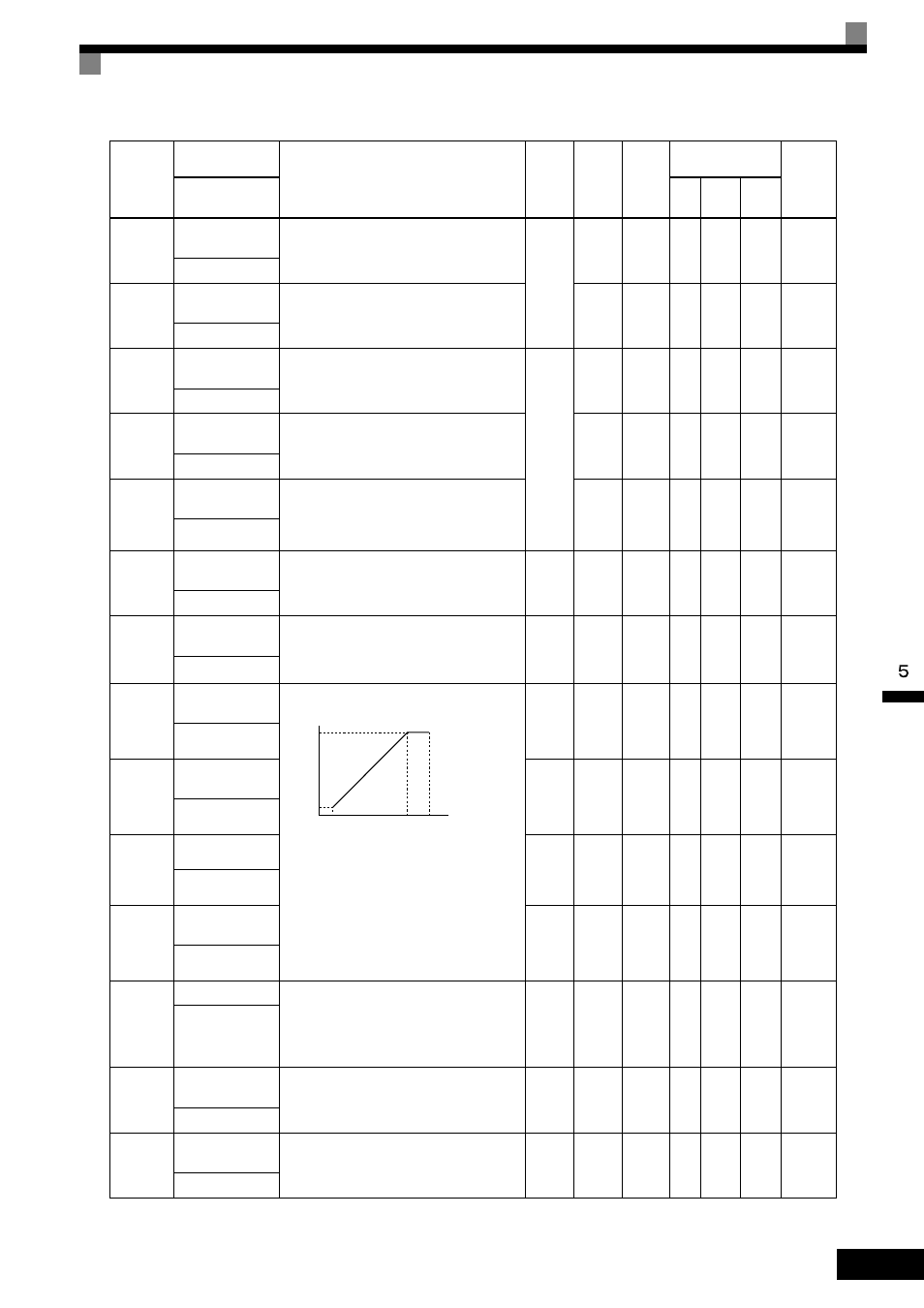
E1-04
Maximum Output
Frequency
To set V/f characteristics in a straight line, set
the same values for E1-07 and E1-09. In this
case, the setting for E1-08 will be disregarded.
Always ensure that the four frequencies are set
in the following manner:
E1-04 (FMAX)
≥ E1-06 (FA) > E1-07 (FB) ≥
E1-09 (FMIN)
40.0 to
120.0
60.0 Hz
*4
No
Q
Q
Q
303H
Max Frequency
E1-05
Maximum Output
Voltage
0.0 to
255.0
*5
200.0
VAC
*4 *5
No
Q
Q
Q
304H
Max Voltage
E1-06
Base Frequency
0.0 to
120.0
60.0 Hz
*4
No
Q
Q
Q
305H
Base Frequency
E1-09
Minimum Output
Frequency
0.0 to
120.0
0.5 Hz
*4
No
Q
Q
A
308H
Min Frequency
E1-13
Base Voltage
Set only when the V/f pattern is finely adjusted
in the constant power area above base speed.
Adjustment is not normally required. If E1-13 =
0.0, then value in E1-05 is used for E1-13.
Auto-Tuning sets this value.
0.0 to
255.0
*5
0.0
VAC
*6
No
A
Q
Q
30CH
Base Voltage
E2-01
Motor Rated Cur-
rent
Sets the motor nameplate full load current in
amperes (A). This value is automatically set
during Auto-Tuning.
2.70 to
54.00
*7
19.60
A
*8
No
Q
Q
Q
30EH
Motor Rated FLA
E2-04
Number of motor
poles
Set the number of motor poles.
This value is automatically set during Auto-
Tuning.
2 to 48 4 poles
No
No
No
Q
311H
Number of Poles
Parameter
Number
Name
Description
Setting
Range
Default
Change
during
Run
Control
Methods
MEMO-
BUS
Register
Display
V/f
Open
Loop
Vector
Flux
Vector
Output voltage (V)
Frequency
(Hz)
VMAX
(E1-05)
VMIN
(E1-10)
FMIN
(E1-09)
FA
(E1-06)
FMAX
(E1-04)
VBASE
(E1-13)