Run command, Mxc functions, Fi g 6.7 mxc fun cti ons – Yaskawa Matrix Converter User Manual
Page 172
Run Command
6-
7
Run Command
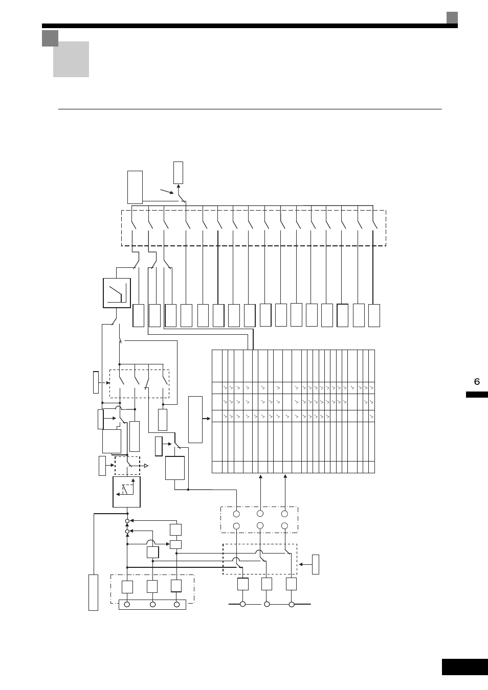
This section explains how to input the Run Command.
MxC Functions
The following block diagram shows the functions available in the MxC.
Option card
other than
A1-14B.
-14B
A/D
1/10
H3-02
H3-03
+
++
+
X1
/1
0
F2-01
L4-05
d1-01
Function selection of
H3-05 (A3 terminal) and
H3-09 (A2 terminal)
L4-05
b1-01
Remote
d2-03
Master Speed
Reference Lower Limit
Option
Multi-function analog input disabled
Multi-function analog input disabled
Multi-function analog input disabled
Second-speed analog selection
Third-speed analog selection
Inverter
Local
Frequency
Reference 1
(d1-01)
= 0
= 1
= 2
= 3
= 4
= 5
= 6
= 7
= 8
= 9
= 10
= 1
1
= 12
= 13
= 14
= 15
Multi-step frequency
reference
d1-17
Jog Frequency
Reference
If the FJOG or RJOG
(Jog frequency reference
of the multi-function
contact input is entered.
Frequency
reference
Frequency
Reference 2
(d1-02)
Frequency
Reference 3
(d1-03)
Frequency
Reference 4
(d1-04)
Frequency
Reference 5
(d1-05)
Frequency
Reference 6
(d1-06)
Frequency
Reference 7
(d1-07)
Frequency
Reference 8
(d1-08)
Frequency
Reference 9
(d1-09)
Frequency
Reference 10
(d1-10)
Frequency
Reference 1
1
(d1-1
1)
Frequency
Reference
12
(d1-12)
Frequency
Reference 13
(d1-13)
Frequency
Reference 14
(d1-14)
Frequency
Reference 15
(d1-15)
Frequency
Reference 16
(d1-16)
=1
=3
=2
=1
=0
=0
=1
=0
=1
=0
=1
=0
=1
=0
MEMOBUS
communications
Proce
ssing
when
loss of
frequenc
y
reference
occurs
Proce
ssing
when
loss o
f
frequ
ency
reference
occ
urs
0V
10V
±
13 bits
A/D
±
13 bits
A/D
±
13 bits
A/D
A
B
C
1
2
3
+10 bits
±
1
1 bits
Code
00
01
02
03
04
05
06
07
08
09
0A
0B
0C
0D
0E
10
11
12
13
14
15
1F
V/f
Open-loop
vector
Flux
vector
Name
Adds to
A1 terminal.
Frequency gain
Second-speed
analog (auxiliary 1)
Third-speed
analog (auxiliary 2)
Output voltage bias
Acceleration/
deceleration time gain
DB current
Over torque and under
torque detection level
Stall prevention level
during operation
Lower limit of output
frequency
Jump frequency
PID feedback
PID target value
Frequency bias 2
Motor temperature input
Forward torque limit
Reverse torque limit
Regenerative torque limit
Torque limit when torque
reference or speed limit
T
orque compensation
Forward and reverse limit
Analog input is not used.
Input level
±
100%,
±
10V
100%, 10V
±
100%,
±
10V
±
100%,
±
10V
100%, 10V
100%, 1V
100%, 10V
100%, 10V
100%, 10V
100%, 10V
100%, 10V
±
100%,
±
10V
±
100%,
±
10V
±
100%,
±
10V
±
100%,
±
10V
100%, 10V
100%, 10V
100%, 10V
±
100%,
±
10V
±
100%,
±
10V
100%, 10V
−
A/D
A/D
±
1
1 bits
Ch1
Ch2
Ch3
A1
terminal
F2-01
A2
terminal
A3
terminal
=0
=1
+10 bits
±
1
1 bits
Note: If
AI-14B is not connected, the MxC
runs as if F2-01 was set to 1 regardless
of the actualF2-01 setting.
A1 input (Refer to Fig.6.8)
−−
−
−
−
−
−
−−
−
−
−
−
Fi
g 6.7
MxC Fun
cti
ons