Pid control applications, Related parameters – Yaskawa Matrix Converter User Manual
Page 260
Individual Functions
6-
95
PID Control Applications
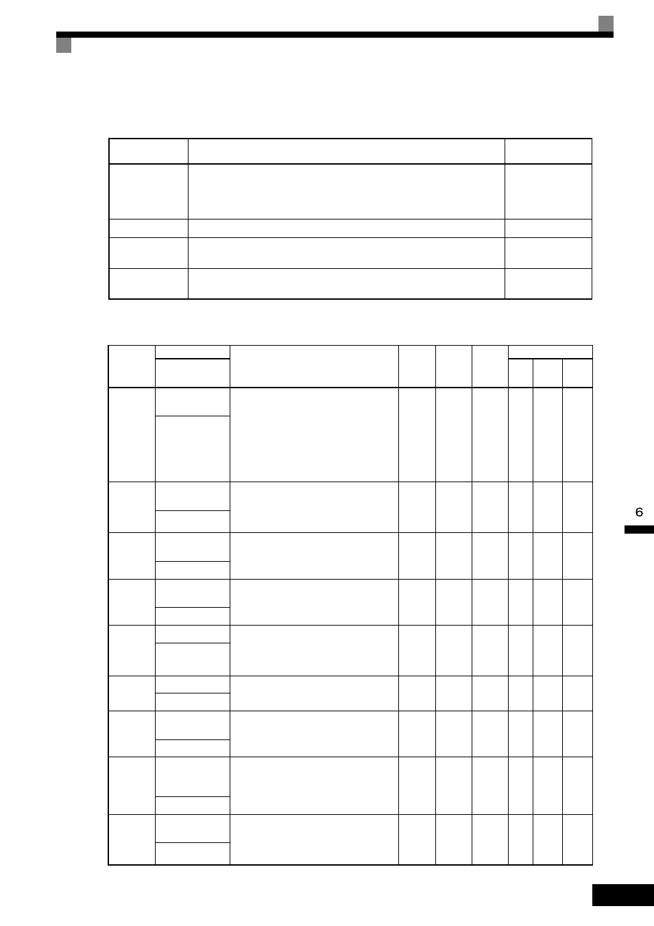
The following table shows examples of PID control applications using the MxC.
Related Parameters
Application
Control Details
Example of
Sensor Used
Speed Control
• Feeds back machinery speed information, and matches speed to the target
value.
• Inputs speed information from other machinery as the target value, and per-
forms synchronous control using the actual speed feedback.
Tachometer
generator
Pressure Control
Feeds back pressure information, and performs parameter pressure control.
Pressure sensor
Flow Rate
Control
Feeds back flow rate information, and controls the flow rate highly accurately. Flow rate sensor
Temperature
Control
Feeds back temperature information, and performs temperature adjustment
control by rotating the fan.
• Thermocouple
• Thermistor
Parameter
Number
Name
Description
Setting
Range
Default
Change
during
Run
Control Methods
Display
V/f
Open
Loop
Vector
Flux
Vector
b5-01
PID Function
Setting
0: Disabled
1: Enabled (Deviation is D-controlled.)
2: Enabled (Feedback value is D-controlled.)
3: PID control enabled (frequency reference
+ PID output, D control of deviation)
4: PID control enabled (frequency reference
+ PID output, D control of feedback
value).
0 to 4
0
No
A
A
A
PID Mode
b5-02
Proportional Gain
Setting
Sets P-control proportional gain as a percent-
age.
P-control is not performed when the setting is
0.00.
0.00
to
25.00
1.00
Yes
A
A
A
PID Gain
b5-03
Integral Time Set-
ting
Sets I-control integral time in 1-second units.
I-control is not performed when the setting is
0.0.
0.0 to
360.0
1.0 s
Yes
A
A
A
PID I Time
b5-04
Integral Limit Set-
ting
Sets the I-control limit as a percentage of the
maximum output frequency.
0.0 to
100.0
100.0%
Yes
A
A
A
PID I Limit
b5-05
Derivative Time
Sets D-control derivative time in 1-second
units.
D-control is not performed when the setting is
0.00.
0.00 to
10.00
0.00 s
Yes
A
A
A
PID D Time
b5-06
PID Output Limit
Sets the upper limit after PID-control as a per-
centage of the maximum output frequency.
0.0 to
100.0
100.0%
Yes
A
A
A
PID Limit
b5-07
PID Offset Adjust-
ment
Sets the offset after PID-control as a percent-
age of the maximum output frequency.
-100.0
to
+100.0
0.0%
Yes
A
A
A
PID Offset
b5-08
PID Primary Delay
Time
Constant
Sets the time constant for low pass filter for
PID-control outputs in 1-second units.
Not usually necessary to set.
0.00 to
10.00
0.00 s
Yes
A
A
A
PID Delay Time
b5-09
PID Output Level
Selection
Select forward/reverse for PID output.
0: PID output is forward.
1: PID output is reverse (highlights the out-
put code)
0 or 1
0
No
A
A
A
Output Level Sel