Yaskawa Matrix Converter User Manual
Page 236
Input Terminal Functions
6-
71
Application Precautions
•
Frequency outputs using UP/DOWN Commands are limited by the frequency reference upper and lower
limits set in parameters d2-01 to d2-03. Here, frequency references from analog frequency reference termi-
nal A1 becomes the frequency reference lower limit. If using a combination of the frequency reference
from terminal A1 and the frequency reference lower limit set in either parameter d2-02 or d2-03, the larger
lower limit will become the frequency reference lower limit.
•
If inputting the Run Command when using Up/Down Commands, the output frequency accelerates to the
frequency reference lower limit.
•
When using Up/Down Commands, multi-step operations are disabled.
•
When d4-01 (Frequency Reference Hold Function Selection) is set to 1, the frequency reference held using
the UP/DOWN functions is stored even after the power supply is turned off. When the power supply is
turned on and the Run Command is input, the motor accelerates to the frequency reference that has been
stored. To reset (i.e., to 0 Hz) the stored frequency reference, turn on the UP or DOWN Command while
the Run Command is on.
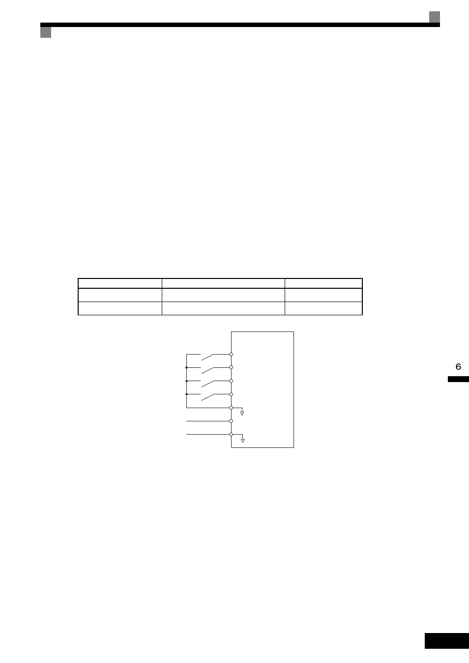
Connection Example and Time Chart
The time chart and settings example when the UP Command is allocated to the multi-function digital input ter-
minal S3, and the DOWN Command is allocated to terminal S4, are shown below.
Fig 6.51 Connection Example when UP/DOWN Commands Are Allocated
Parameter
Name
Set Value
H1-01
Multi-function input (terminal S3)
10
H1-02
Multi-function input (terminal S4)
11
0 to 10 V analog
signal
Forward
operation/Stop
Reverse
operation/Stop
Up command
Down command
Sequence
common
Frequency
reference lower
limit
MxC
S1
S2
S3
S4
SC
A1
AC